Spinal orthotic devices

a technology of orthotics and supporting components, applied in the field of spinal orthotics, can solve the problem that spinal orthotics cannot make use of all elements of the modular system, and achieve the effect of increasing or decreasing the support properties

Inactive Publication Date: 2010-02-16
ZOURS CLAUDIA
View PDF8 Cites 51 Cited by
  • Summary
  • Abstract
  • Description
  • Claims
  • Application Information

AI Technical Summary

Benefits of technology

[0008]Therefore, the object of the present invention is to provide a modular system for spinal orthotic devices such that its spinal orthotic devices can be adapted flexibly to a great extent to the particular symptoms and the patient's progress in recovery. With the smallest possible number of elements, the largest possible variety of orthotic devices should configurable so that they can be used with a variety of diseases and their supporting properties can be increased or decreased.
[0010]The seven elements described in Claim 1 (see also a1) to c1), e1), g1), h1) and i1))—the lower abdominal corset (also known as a lumbar spinal corset), the upper abdominal corset (also known as a shoulder strap system), the corset supporting element (also known as a basic truss pad), the thoracic corset (also known as a thoracic orthotic or thoracic orthotic device), the curved supporting clasp on a corset supporting element, the supporting element and the abdominal truss pad—constitute the basic elements of the basic modular system from which the inventive orthotic devices can be configured. Some of the basic elements of the modular kit are needed for various orthotic devices and thus are reusable if the patient needs a different orthotic device. The modular system also allows therapeutically correct training of the spine, wherein elements are removed successively from a more complex orthotic device, which is thus dismantled incrementally. If there is a delay in recovery, it is possible at any time to return an orthotic device that has been removed too soon, to thereby return to a higher level of support.
[0013]The nine elements described in Claim 10 (see a2) to i2))—the lower abdominal corset, the upper abdominal corset, the basic truss pad, the lumbar extension for the basic truss pad, the thoracic corset, the connecting element, the bridging frame, the supporting element and the abdominal truss pad—are the basic elements of the additional modular system with which at least seven different orthotic devices can be configured according to this invention. Some of the basic elements of the modular kit are needed for different orthotic devices and are thus reusable if the patient needs a different orthotic device. The modular system also allows therapeutically correct training in that elements are removed successively from a more complex orthotic device, which is therefore decreased incrementally. It is possible at any time to reassemble the orthotic device that has been removed too soon in the event of a delay in recovery in order to thereby return to a higher level of support.
[0015]Since the joints of the sectional truss pad usually also allow a certain mobility of the individual sections in relation to one another in the sagittal plane, it is advisable to provide a fixation element within the modular system, so that it can be placed in a posterior position on the sectional truss pad, so that the sections of the truss pad are secured immovably in relation to one another in the sagittal plane.

Problems solved by technology

The object for which patent protection is sought is such a spinal orthotic device that can be configured using this modular system, although the spinal orthotic device cannot make use of all elements of the modular system in principle.

Method used


Image

  • Spinal orthotic devices
  • Spinal orthotic devices
  • Spinal orthotic devices

Examples


Embodiment Construction

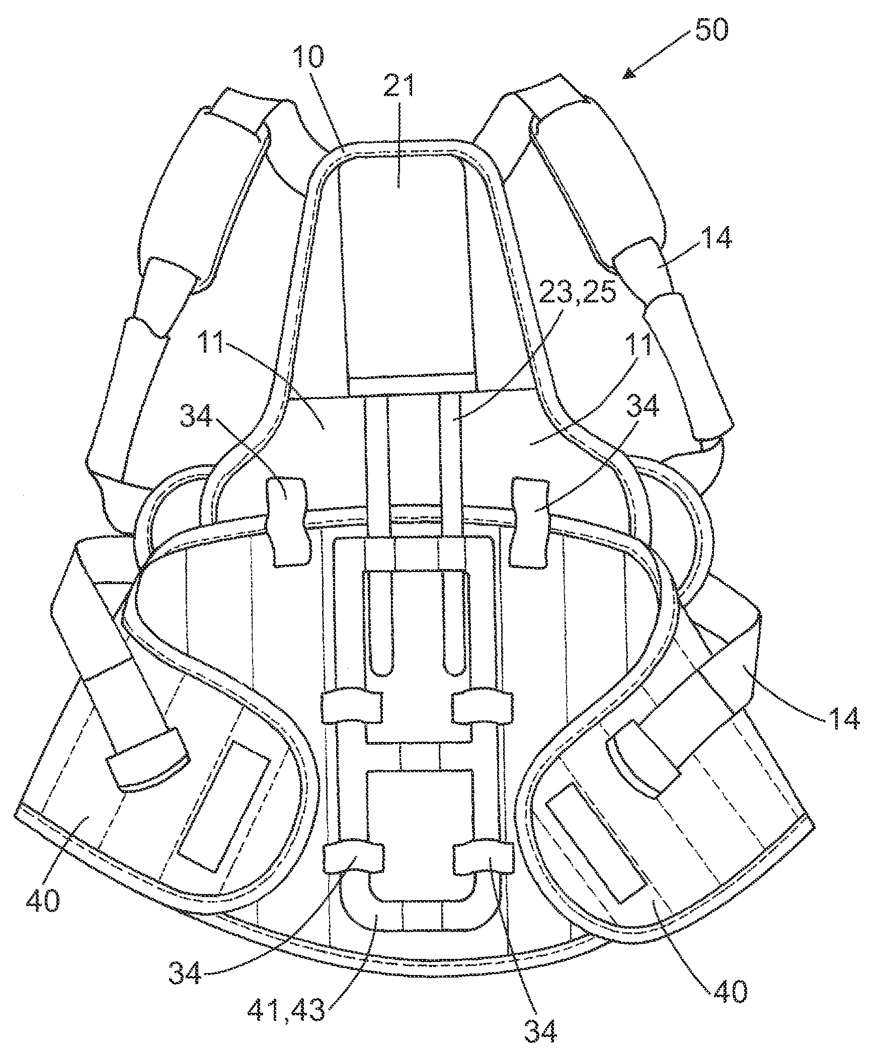
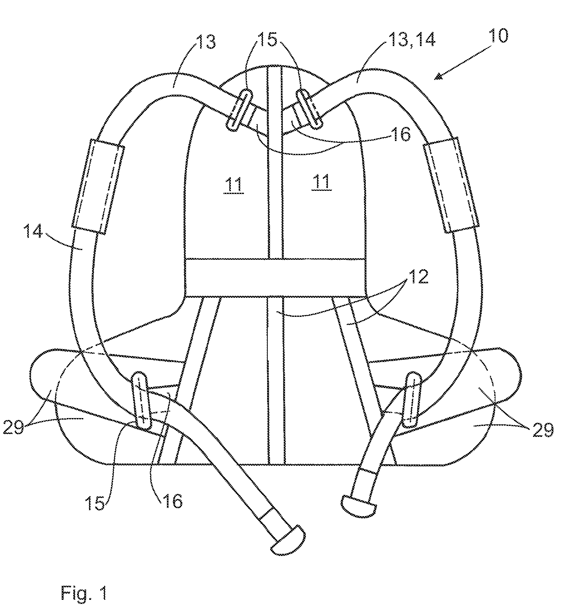
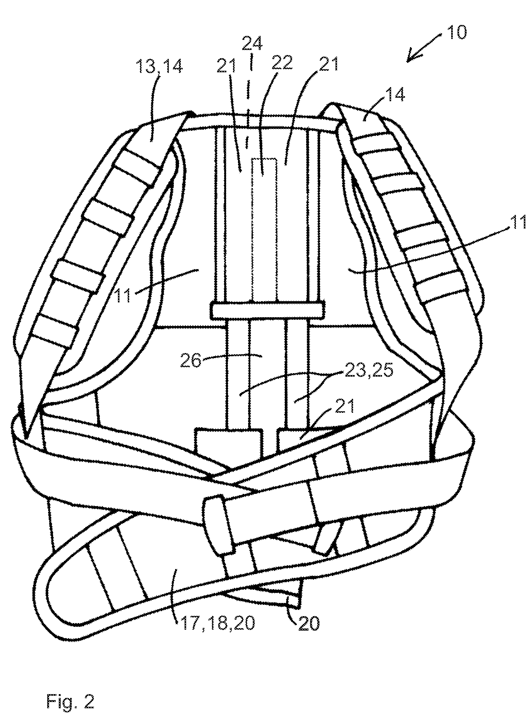
[0053]FIG. 1 shows an inventive thoracic spinal orthotic device 10, as seen in a view from the rear. The triangular posterior part 11 is shown with very rounded corners and also with stripes 12 in the form of cloth strips or parts of a hook-and-loop fastener (also called VELCRO-type closure parts). This posterior part 11 is designed to be in symmetry with the spine and / or a vertical line. On the cranial end of the posterior part 11 two inelastic belts 14 of the shoulder belt system 13 are arranged in the area of the spine. Belt holders 15 consisting essentially of a closed curved plastic part are used here. These belt holders 15 are attached to the posterior part 11 by elastic bands 16. The elastic bands 16 run diagonally away from the spine, with the bands arranged in an ascending pattern to the shoulder. The inelastic belts 14 of the shoulder belt system 13 are arranged on the belt holders 15. These run toward the lower belt holders 15 which are also arranged on the posterior part...


PUM


Abstract

The invention relates to a spinal orthotic device configured from one or more elements of a modular system, comprising the following elements:a lower abdominal corset (40, 120),an upper abdominal corset (17, 130) that can be attached cranially to the lower abdominal corset (40, 120),a corset supporting element (41) that can be secured posteriorly in the lower abdominal corset (40, 120) and is arranged along the lumbar spine, supporting the spine while restricting sagittal mobility,a thoracic spinal corset (10, 200) that can be attached cranially to the lower abdominal corset (40, 120),at least one curved supporting clasp (47) that can be inserted posteriorly optionally into a bandage of a lower abdominal corset (40, 120) and an upper abdominal corset (17, 130) or into an bandage of a lower abdominal corset (40, 120) and a thoracic spinal corset (10, 200), said curved supporting clasp being attached to a corset supporting element (41) for correction of lordosis and for restriction of sagittal and frontal mobility in the area of the lumbar spine,at least one supporting element (23, 160) which can optionally be secured cranially in the thoracic spinal corset (10, 200) and caudally to the corset supporting element (41, 150) and extends laterally along the spine to align and relieve the spine in the sagittal plane,and an abdominal truss pad (190) that can be attached ventrally to a lower abdominal corset (40, 120) for correction of lordosis of the lumbar spine and increasing the intra-abdominal pressure.

Description

BACKGROUND OF THE INVENTION[0001]1.Field of Invention[0002]The present invention relates to the field of spinal orthotic devices, which are configured as elements of a modular system.[0003]Such a spinal orthotic device is known from Unexamined German Patent DE 103 29 454 A1, among others.[0004]Various symptoms in the spinal area are treated with a variety of orthotic devices which support and / or align the spine in the affected portions and / or restrict its mobility in the various planes. The supporting behavior and the stiffness of the orthotic device are determined by the patient's progress in recovery. In the past, new orthotic devices would be prescribed repeatedly in the course of recovery so that their supporting behavior or rigidity would take into account the patient's indication as well as the patient's current progress in recovery.[0005]To reduce costs for medical insurance carriers, modular systems for orthotic devices that can be adapted approximately to the area of the sp...

Claims


Application Information

Patent Timeline
IPC IPC(8): A61F5/00
CPCA61F5/028A61F5/026
Inventor ZOURS, CLAUDIA
Owner ZOURS CLAUDIA
Why Eureka
Try Eureka