
Method and device for determining an activation threshold

a laser diode and activation threshold technology, applied in the direction of laser details, semiconductor lasers, electrical apparatus, etc., can solve the problems of reducing the optical power of the laser diode, unable to ensure the reliability and accuracy of the obtained results, and the output signal of the differential amplifier is smaller. achieve the effect of accurate reproduction and reliably determined

Active Publication Date: 2010-02-09
ATMEL CORP
View PDF9 Cites 4 Cited by
  • Summary
  • Abstract
  • Description
  • Claims
  • Application Information

AI Technical Summary

Benefits of technology

This approach allows for reproducibly accurate determination of the laser threshold, reducing sensitivity to measuring actions and enhancing control over optical power and output signals by competing feedbacks, ensuring stable operation.

Problems solved by technology

If the laser diode emits a relatively high optical power, the photodiode supplies a high photocurrent to the feedback signal input of the differential amplifier, which makes the output signal of the differential amplifier smaller and thereby reduces the laser diode optical power.
A sufficient reliability and accuracy of the obtained results are therefore not readily assured.

Method used


Image

  • Method and device for determining an activation threshold
  • Method and device for determining an activation threshold
  • Method and device for determining an activation threshold

Examples


Embodiment Construction

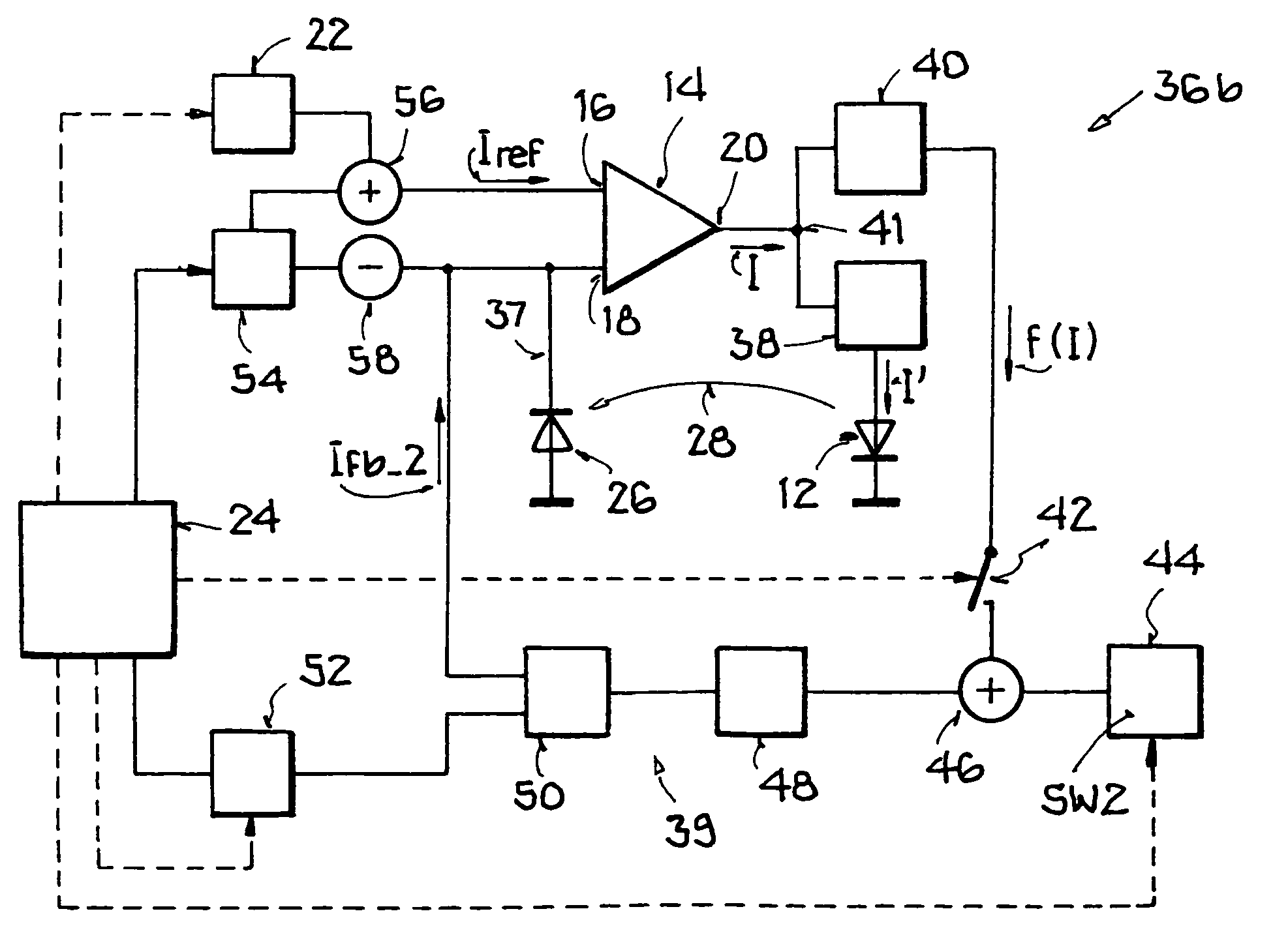
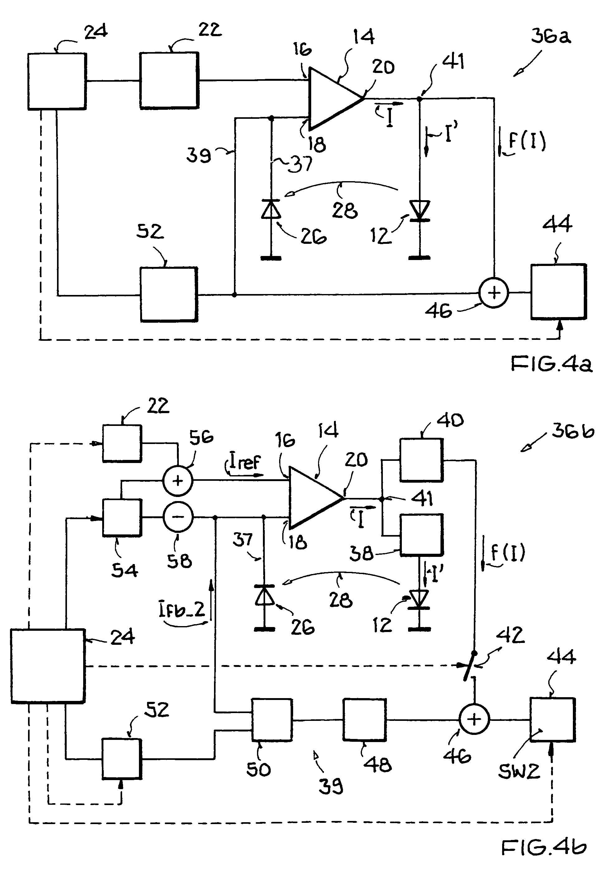
[0043]FIG. 1 shows a drive circuit 10, which drives a laser diode 12. Drive circuit 10 has a differential amplifier 14, which has a reference signal input 16, a feedback signal input 18, and an output 20, and a reference signal generator 22, a controller 24, and a photodiode 26. Reference signal input 16 is supplied by reference signal generator 22, which is controlled by controller 24. Photodiode 26 is connected to feedback signal input 18, and during operation of drive circuit 10 and laser diode 12, it receives part of the optical power emitted by laser diode 12 through an optical coupling 28 and converts it into a photocurrent. The photocurrent functions as feedback signal Ifb. Differential amplifier 14 provides a current I as a drive signal for laser diode 12, which depends on the amplification factor G of differential amplifier 14 and the difference of the signal at reference signal input 16 and feedback signal input 18. In this way, the power emitted by laser diode 12 and the ...


PUM


Abstract

A method is provided for determining a laser threshold of a laser diode, which is operated by a drive circuit as a function of a first signal in a first feedback and a second signal in a second feedback, the first feedback being supplied via an optical coupling of an optical output signal of the laser diode. The method is characterized in that the second feedback is supplied by an electrical signal picked up between the drive circuit and the laser diode, the electrical signal is compared with an adjustable activation threshold, only a portion of the electrical signal that exceeds the adjustable activation threshold is transmitted to the drive circuit in such a way that the second feedback is active only when such a portion occurs, the adjustable activation threshold is changed in such a way that the activity state of the second feedback changes, and the laser threshold of the laser diode is determined as a function of the value of the adjustable activation threshold during a change in the activity state of the second feedback. Furthermore, a drive circuit is presented which carries out the method.

Description

[0001]This nonprovisional application claims priority under 35 U.S.C. § 119(a) on German Patent Application No. DE 102005009317, which was filed in Germany on Feb. 18, 2005, and which is herein incorporated by reference.BACKGROUND OF THE INVENTION[0002]1. Field of the Invention[0003]The present invention relates to a method for determining a laser threshold of a laser diode, which is operated by a drive circuit as a function of a first signal in a first feedback and a second signal in a second feedback, the first feedback being supplied via an optical coupling by an optical output signal of the laser diode.[0004]The invention relates furthermore to a drive circuit, which determines the laser threshold of a laser diode, wherein the drive circuit generates a drive signal and the laser diode an output signal, dependent on the drive signal, with a first feedback and a second feedback, the first feedback being set up to supply a portion of the output signal via an optical coupling.[0005]...

Claims


Application Information

Patent Timeline
Patent Type & Authority Patents(United States)
IPC IPC(8): H01S3/00
CPCH01S5/042H01S5/0683H01S5/06812
Inventor KNOTZ, HERBERT
Owner ATMEL CORP
Learn More