
Vehicular lamp

a technology of vehicle lamps and lamps, which is applied in the manufacture of electric discharge tubes/lamps, electrode systems, lighting and heating apparatus, etc., can solve the problems achieve the effect of poor light utilization efficiency

Inactive Publication Date: 2010-02-02
KOITO MFG CO LTD
View PDF5 Cites 9 Cited by
  • Summary
  • Abstract
  • Description
  • Claims
  • Application Information

AI Technical Summary

Benefits of technology

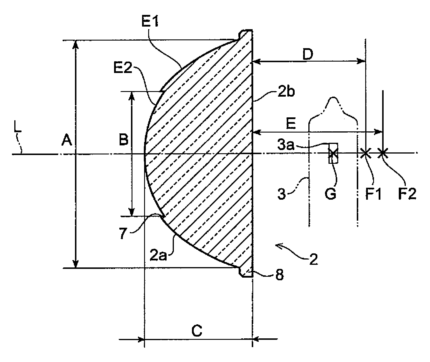
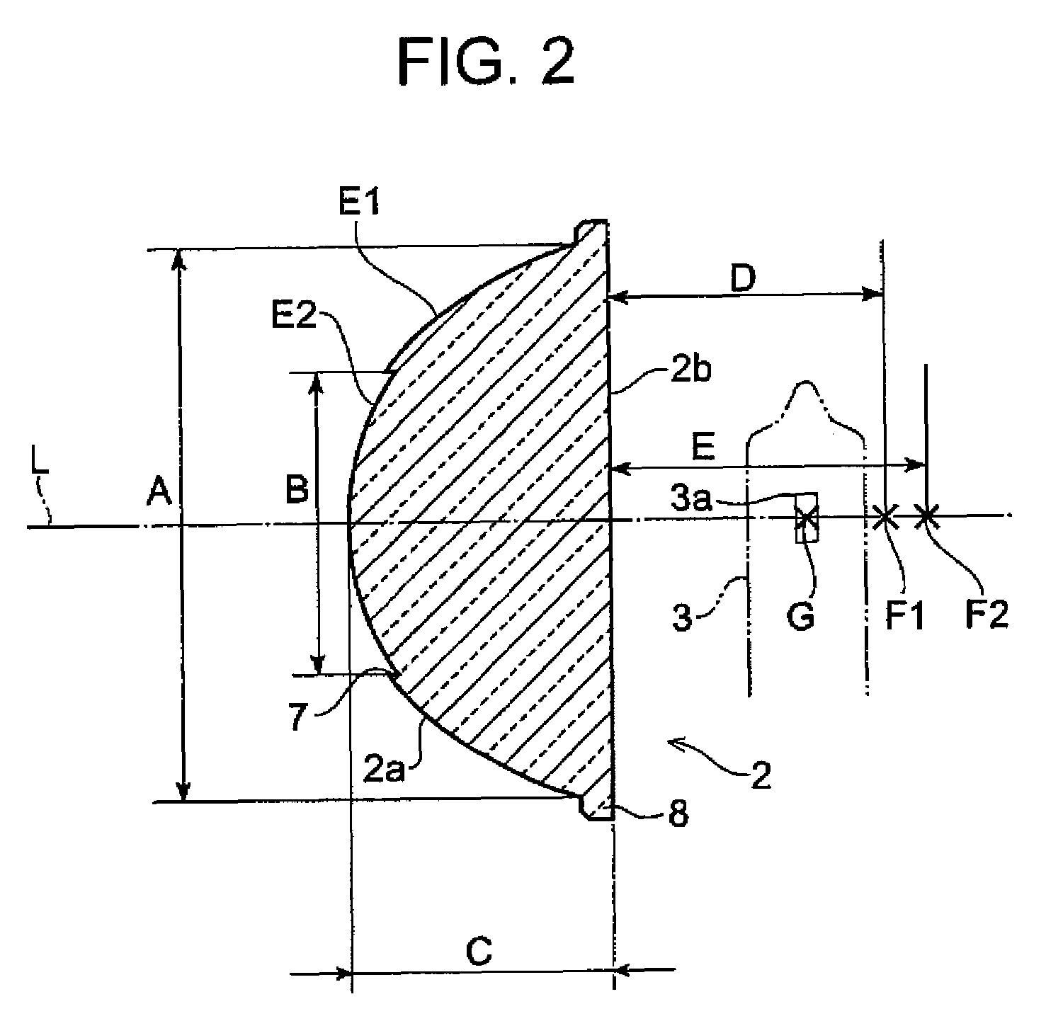
The present invention provides a vehicular lamp that can mitigate redness at the outer periphery of a light distribution pattern and create a uniform light approaching white without using a reflecting mirror. This is achieved by using a projection lens with multiple lens areas that have different focal points, which are placed in consecutive order. The light emission portion is preferably shaped long in the vehicle width direction and short in the vehicle height direction, and at least a portion of the outermost periphery of the projection lens is preferably formed with a frosted light diffusing surface. The technical effects of this invention include a reduction in redness at the outer periphery of a light distribution pattern and a more uniform light approaching white.

Problems solved by technology

Therefore, problems arise in which the shape of the light bulb is prone to projection on a light distribution pattern, and furthermore, the outermost periphery of the light distribution pattern appears nearly red due to a chromatic aberration of the lens.
A further problem results from using the reflecting mirror, which worsens light utilization efficiency.

Method used


Image

  • Vehicular lamp
  • Vehicular lamp
  • Vehicular lamp

Examples


Embodiment Construction

[0021]Preferred embodiments of a vehicular lamp according to the present invention will be described in detail below with reference to the drawings.

[0022]Referring to FIG. 1, a vehicular lamp 1 is a direct optical type of headlamp capable of switching between low and high beams. The vehicular lamp 1 creates a light beam for overlapping on a high-beam pattern, without using a reflecting mirror. The vehicular lamp 1 is used with an aim to approach an upper limit value of a standard value for a high beam, for the purpose of extending a remote radiation distance of the high beam. Furthermore, the vehicular lamp 1 is provided with a glass projection lens 2 with a generally hemispheric shape, a halogen bulb 3 that emits white light and is used as a light source, and a housing 4 for protecting the halogen bulb 3. The housing 4 is formed from a body portion 5 and a cover 6. The body portion 5 has a cylindrical shape and an opening portion 5a that is formed as a side hole for inserting the h...


PUM


Abstract

A vehicular lamp includes a projection lens with an optical axis extending in a longitudinal direction of a vehicle and a light source with a light emission portion. The light emission portion is directly incident to the projection lens. The projection lens has a plurality of lens areas with different focal points, with the lens areas centered on the optical axis and disposed on generally concentric circles. The focal points corresponding to the plurality of lens areas have respectively different positions on the optical axis.

Description

BACKGROUND OF INVENTION[0001]1. Field of the Invention[0002]The present invention relates to a vehicular lamp applicable to a low or high beam of a headlamp, a backup lens, a fog lamp, a clearance lamp, and the like, which is particularly useful as an auxiliary beam for a headlamp.[0003]2. Background Art[0004]Related art from this field includes Japanese Patent Application Laid-Open (Kokai) No. 2001-6408. A vehicular headlamp described therein is provided with a light bulb disposed between a reflecting mirror and a cylindrical lens, and between a lens and the reflecting mirror. Light emitted from the light bulb is formed from light incident to the reflecting mirrors and light directly incident to the lens so as to create a predetermined illumination from the reflective light and the direct light. In Utility Model Registration No. 2543306, a hemispheric convex lens is disclosed that creates a predetermined illumination from the light reflected by the reflecting mirror and the light p...

Claims


Application Information

Patent Timeline
Patent Type & Authority Patents(United States)
IPC IPC(8): B60Q1/00B60Q3/00F21W107/10F21Y101/00
CPCF21S48/1283F21S48/1258F21S41/255F21S41/275
Inventor TENDO, HIROKITAJIMA, TAKEHIKO
Owner KOITO MFG CO LTD
Learn More