
Band pass filter

a band pass filter and filter technology, applied in the field of multi-layered band pass filters, can solve the problems of deteriorating wireless telecommunication system performance and increasing the total volume of filters, and achieve the effects of improving stop characteristics, constant ratio, and high impedan

Inactive Publication Date: 2010-01-19
SAMSUNG ELECTRO MECHANICS CO LTD
View PDF19 Cites 3 Cited by
  • Summary
  • Abstract
  • Description
  • Claims
  • Application Information

AI Technical Summary

Benefits of technology

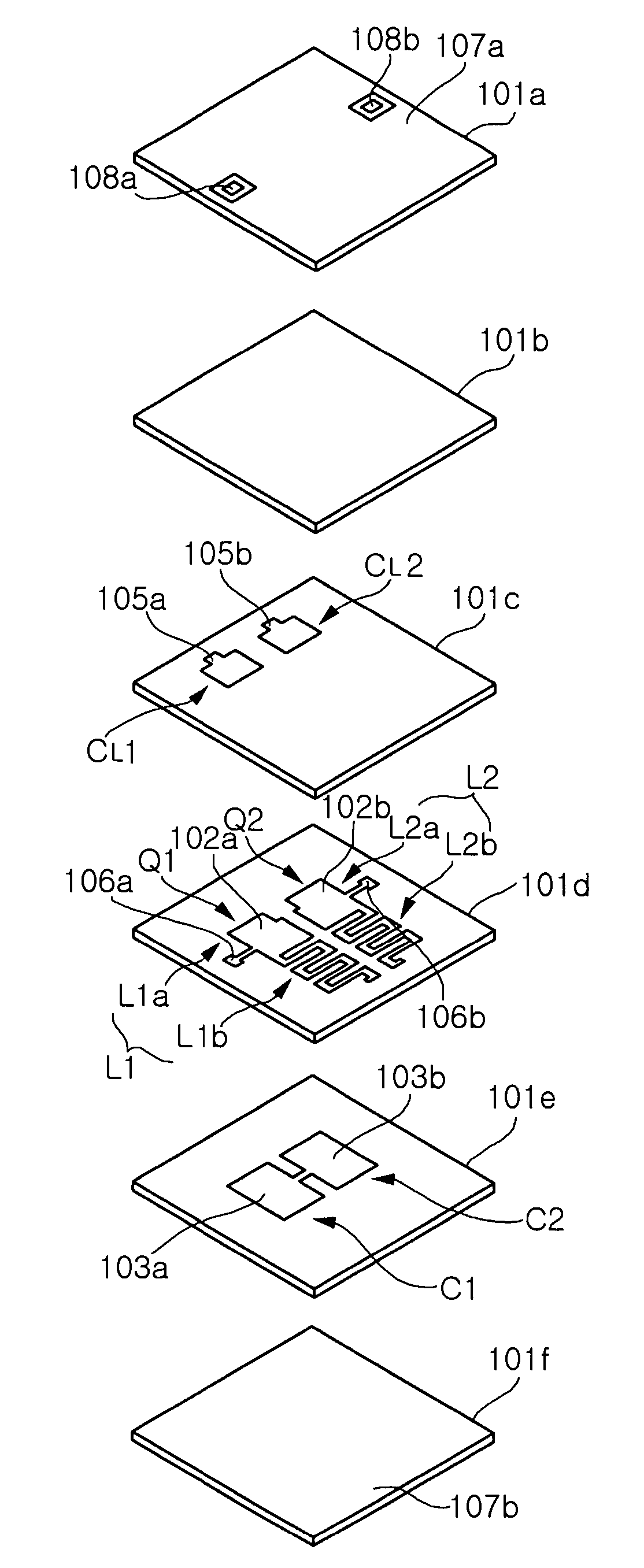
The present invention provides a multi-layered band pass filter that can improve the stop characteristic and attenuation characteristic of a pass band. The filter includes a ceramic laminated body with multiple layers and patterns of inductors and capacitors. The high impedance portion and low impedance portion of the filter are maintained in a constant ratio using a step-impedance resonator, which reduces the overall size of the filter. Additionally, the filter can improve the stop characteristic for additional components in a lower band by coupling a notching capacitor to the tip of the high impedance portion of the resonator. The filter also includes patterns of load capacitors and ground planes to further enhance its performance.

Problems solved by technology

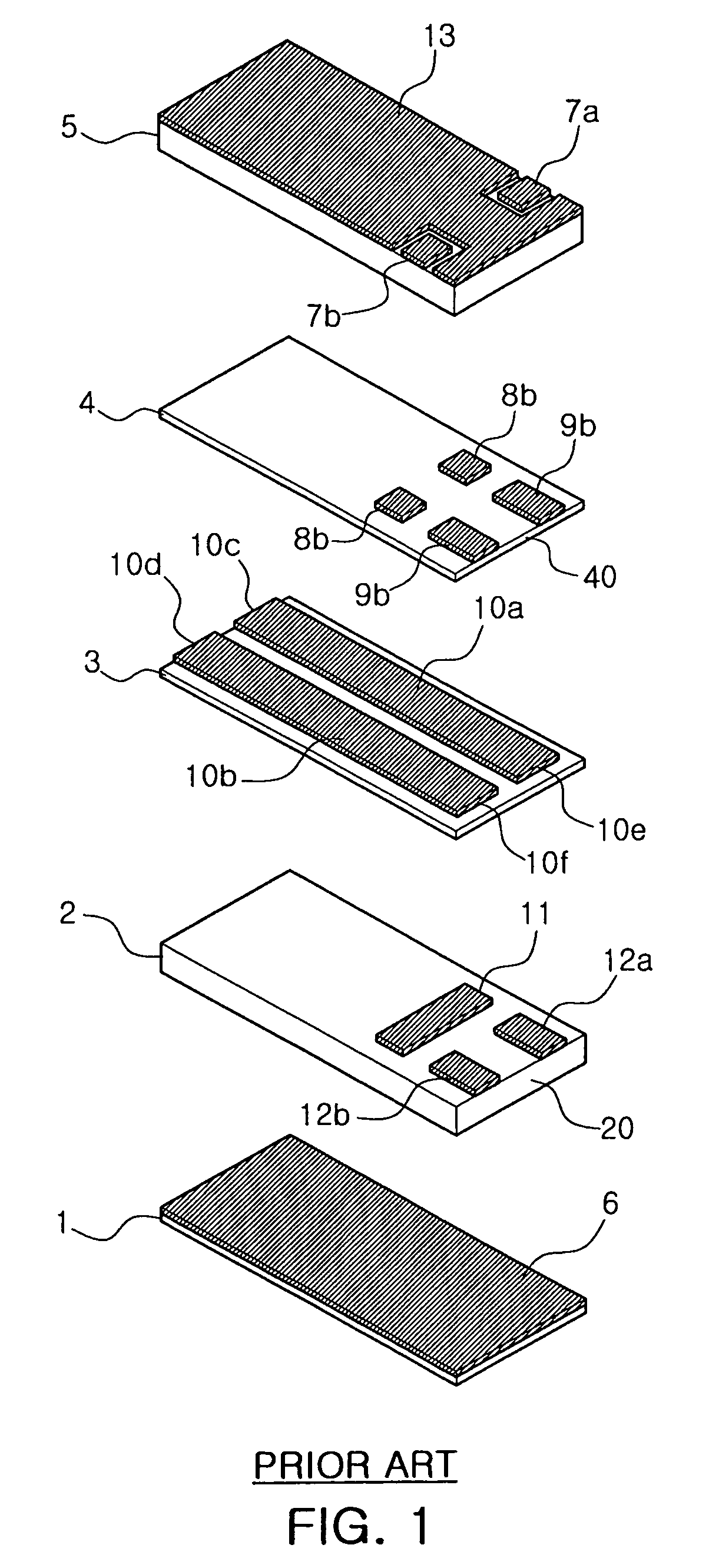
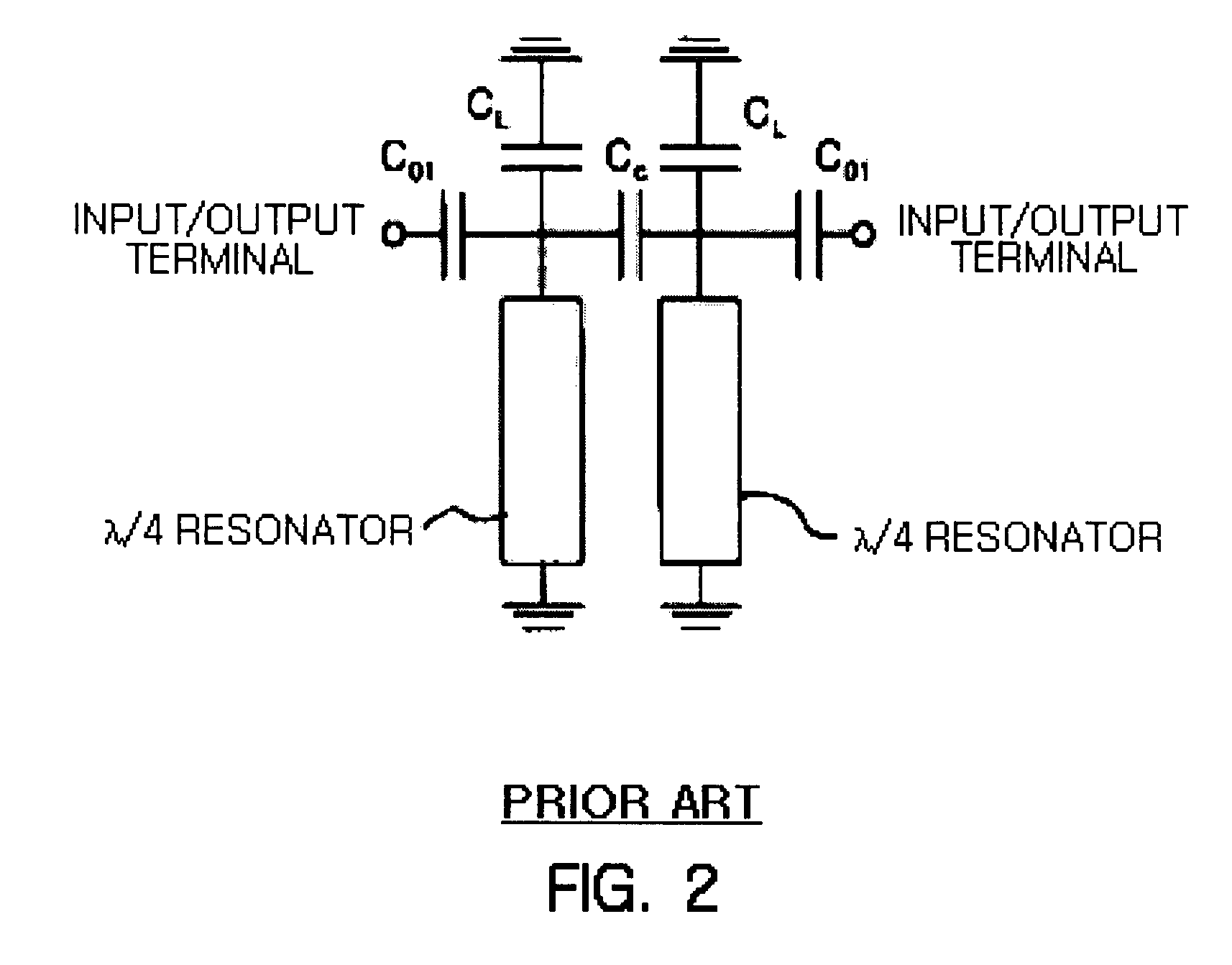
However, the resonators used in the conventional multi-layered band pass filter have a problem that the total volume of the filter is increased as their frequencies become low because the resonators are in the straight-line form having a constant width and their entire λ / 4 length is used.
Also, since the input / output terminals have the same shape as the capacitor and are coupled to the resonators, an insertion loss of the filter is high in the multi-layered structure due to the change in process, for example the dimensional difference between an upper layer and a lower layer or the positional changes, which leads to the deteriorated performance of wireless telecommunication systems.

Method used


Image

  • Band pass filter
  • Band pass filter
  • Band pass filter

Examples


Embodiment Construction

[0028]Exemplary embodiments of the present invention will now be described in detail with reference to the accompanying drawings. However, the description proposed herein is just a preferable example for the purpose of illustrations only, not intended to limit the scope of the invention, so it should be understood that other equivalents and modifications could be made thereto without departing from the spirit and scope of the invention. Therefore, the shapes and sizes of parts shown in the accompanying drawings may be expressed exaggeratedly for clarity and the same parts have the same reference numerals in the accompanying drawings.

[0029]FIG. 3 is a diagram illustrating a configuration of a multi-layered band pass filter according to an exemplary embodiment of the present invention, and FIG. 4 is an equivalent circuit view of the multi-layered band pass filter as shown in FIG. 3.

[0030]The multi-layered band pass filter according to an exemplary embodiment of the present invention i...


PUM


Abstract

There is provided a multi-layered band pass filter capable of improving a stop characteristic out of a pass band and reducing the entire size of the filter. The multi-layered band pass filter includes a ceramic laminated body having at least first to fifth dielectric layers laminated sequentially therein; first and second resonators having symmetrical patterns of first and second inductors formed on the first dielectric layer, and symmetrical patterns of first and second capacitors formed on the second dielectric layer so that they are at least partially overlapped with the patterns of the first and second inductors; a pattern of first and second load capacitors electrically capacitively coupled respectively to ends of the first and second resonators formed on the third dielectric layer; a pattern of first and second notching capacitors electrically capacitively coupled respectively to the other ends of the first and second resonators formed on the third dielectric layer; and first and second ground planes formed respectively on the fourth and fifth dielectric layers, wherein each of the patterns of the first and second inductors is composed of a low impedance portion formed of wide-width lines and a high impedance portion formed of meander-type narrow-width lines from the low impedance portion.

Description

CROSS-REFERENCE TO RELATED APPLICATIONS[0001]This application claims the priority of Korean Patent Application Nos. 2006-0105227 and 2006-0105228, filed on Oct. 27, 2006, in the Korean Intellectual Property Office, the disclosures of which are incorporated herein by reference.BACKGROUND OF THE INVENTION[0002]1. Field of the Invention[0003]The present invention relates to a multi-layered band pass filter, and more particularly, to a multi-layered band pass filter capable of improving a stop characteristic out of a pass band and reducing the entire size of communication systems.[0004]2. Description of the Related Art[0005]In general, a band pass filter, which is a radio frequency (RF) device that is composed of input / output terminals that play a role in the input / output of a frequency signal; and a combination of a plurality of electrode patterns and a plurality of resonators having frequency selectivity, functions to pass only a frequency signal within a pass band out of frequency si...

Claims


Application Information

Patent Timeline
Patent Type & Authority Patents(United States)
IPC IPC(8): H03H7/00H01P7/00
CPCH01P1/20345
Inventor CHO, YUN HEEPARK, YUN HWI
Owner SAMSUNG ELECTRO MECHANICS CO LTD
Learn More