
Roof edging system

a roof edging and water proofing technology, applied in the direction of roof tools, snow traps, building roofs, etc., can solve the problems of unexpected removal of the fascia from the roof edging system, complex multi-component roof edging systems, and requiring installation, so as to achieve quick security

Inactive Publication Date: 2010-01-19
METAL ERA
View PDF28 Cites 18 Cited by
  • Summary
  • Abstract
  • Description
  • Claims
  • Application Information

AI Technical Summary

Benefits of technology

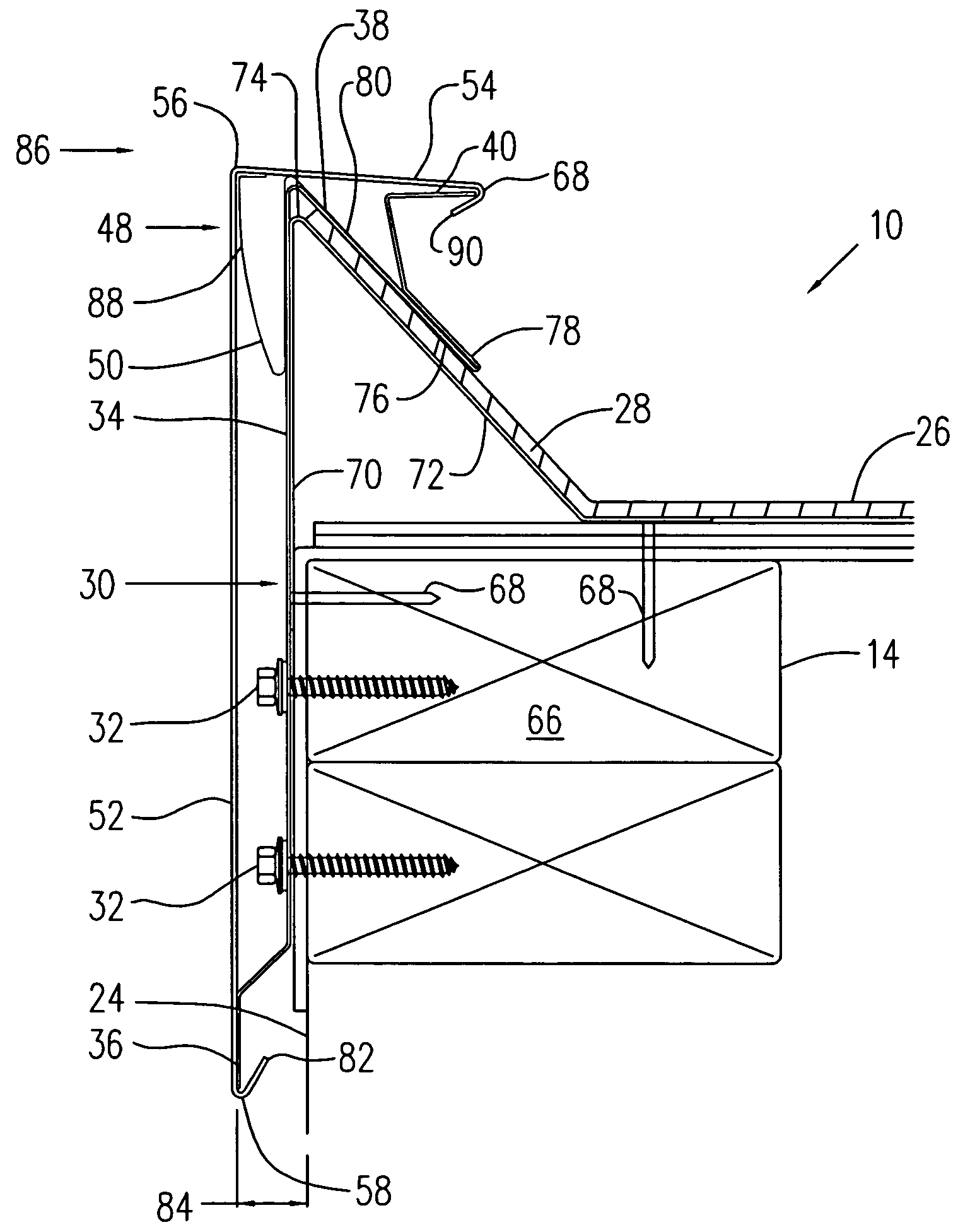
[0006]The present invention is directed to a roof edging system that solves the aforementioned problems. A roof edging system for providing a functional and aesthetically pleasing appearance of a periphery of a building roof is provided. The system includes a rail positioned about an upper perimeter of a building. The rail is also constructed to sealingly engage a roofing membrane placed about the roof. A cover or fascia member snap fittingly engages the rail and is secured to the rail without fasteners. Such a construction provides a roof edging system that can be quickly secured to a building and provides an exterior surface that is free of perforations.

Problems solved by technology

Understandably, such multi-component roof edging systems are relatively complex and require installation by skilled technicians in order to ensure an aesthetic and properly functioning roof edge.
Failure to securely connect the fascia to the roof edging system could result in unexpected removal of the fascia from the roof edging system during windy conditions.

Method used


Image

  • Roof edging system
  • Roof edging system
  • Roof edging system

Examples


Embodiment Construction

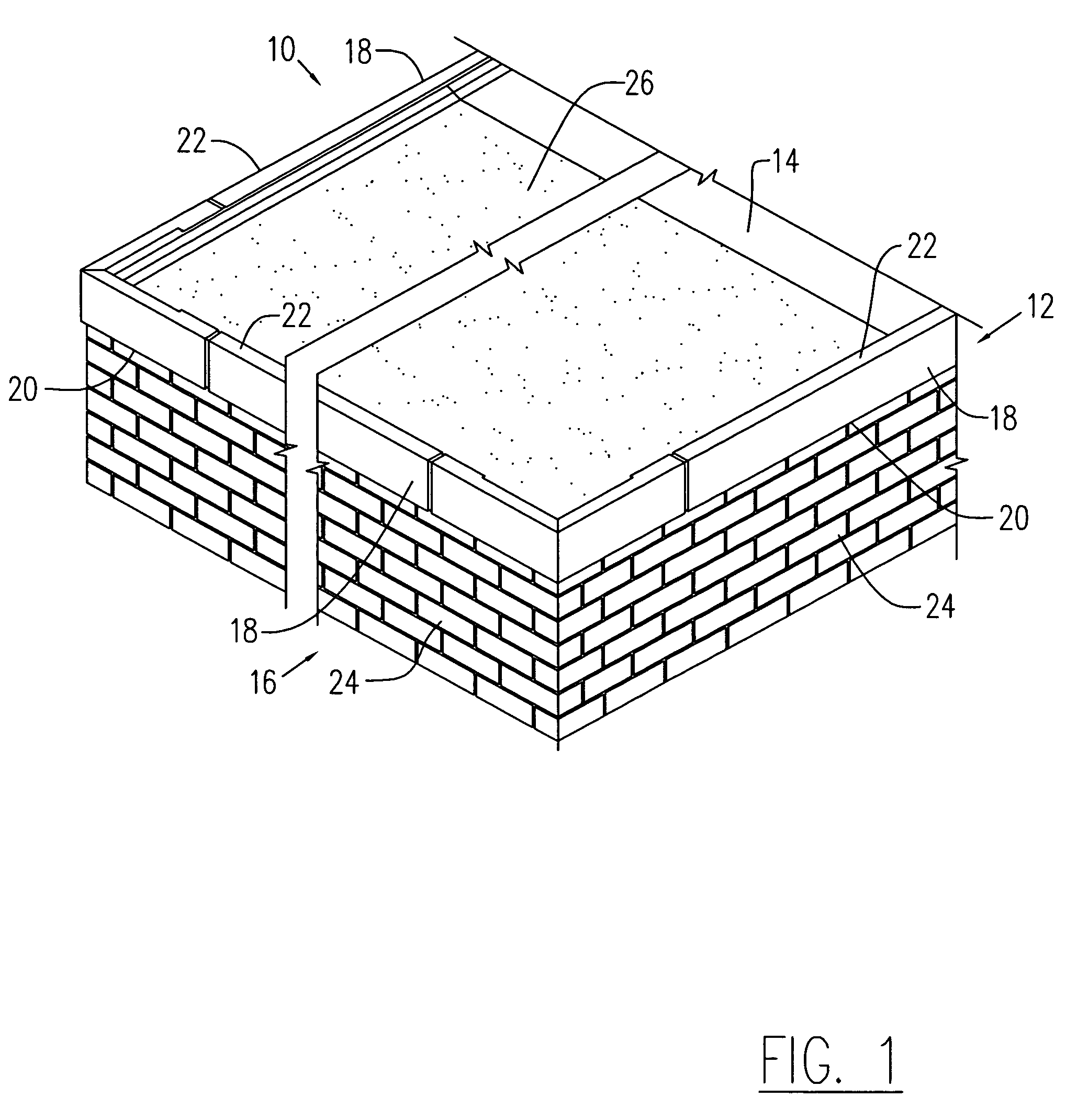
[0018]FIG. 1 shows a roof edging system 10 according to the present invention positioned about a perimeter 12 of a roof 14 of a building 16. The roof edging system 10 includes a plurality of side sections 18 which are oriented to generally encircle the perimeter 12 of building 16. Each side section 18 includes a wall portion 20 and a roof portion 22. The wall portions 20 are generally orientated such that they extend in a direction generally parallel to a respective wall 24 of building 16. Comparatively, roof portions 22 extend in a direction generally parallel to roof 14. A roof seal or membrane 26 generally extends about the roof 14 within the area generally circumscribed by the roof edging system 10. Membrane 26 is sealingly connected to the roof edging system 10 such that precipitation collected within perimeter 12 of roof 14 can be directed to a scupper (not shown) or other drain system. Such construction ensures that the roof system of building 16 is weather tight.

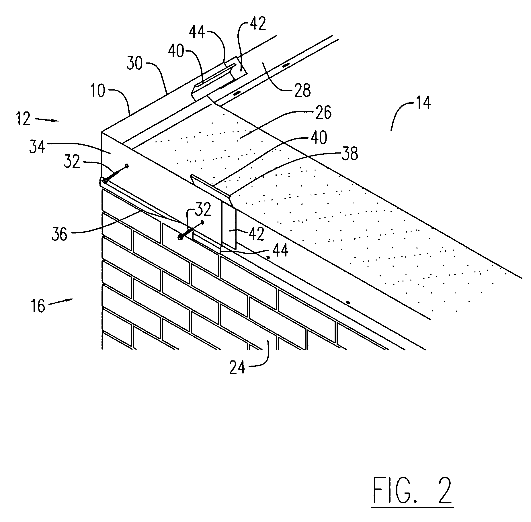
[0019]FIG. 2...


PUM


Abstract

A roof edging system for providing a functional and aesthetically pleasing appearance of a periphery of a building roof is provided. The system includes a rail positioned about an upper perimeter of a building. The rail is also constructed to sealingly engage a roofing membrane placed about the roof that is free of perforations. A cover or fascia engages the rail and is secured to the rail without fasteners. Such a construction provides a roof edging system, which can be quickly secured to a building and provides an exterior surface.

Description

FIELD OF THE INVENTION[0001]The present invention relates to roof edging and water proofing systems, and more specifically to a roof edging system having an opening-free fascia member snap fittingly engaged to an underlying rail member.BACKGROUND OF THE INVENTION[0002]Many types of buildings have flat roofs with exposed roof edges that must be sealed in order to prevent water from leaking into the interior of the building. The roofs on buildings of this type generally include fully adhered or mechanically attached single ply roofs or built up or modified roof systems, among others. In order to effectively seal the roofs of these buildings, many different roof edging systems, such as fascias and copings, have been developed which cooperate with a roofing membrane placed over the roof to prevent water from entering a building between the membrane and the remainder of the building.[0003]Known roof edging systems generally include a rail constructed to be attached to the building struct...

Claims


Application Information

Patent Timeline
Patent Type & Authority Patents(United States)
IPC IPC(8): E04D3/00
CPCE04D13/155
Inventor INZEO, JOSEPH A.KITTILSTAD, SCOTT A.
Owner METAL ERA
Learn More