Breaker tool with vibration damped handle device

a technology of vibration damping and handle device, which is applied in the field of breaker tools, can solve the problems of vibration damping along the entire movement range load on the swing arms of the handle device, etc., and achieve the effect of optimum vibration damping and extended service life of these parts

Active Publication Date: 2010-01-05
ATLAS COPCO AIRPOWER NV
View PDF23 Cites 9 Cited by
  • Summary
  • Abstract
  • Description
  • Claims
  • Application Information

AI Technical Summary

Benefits of technology

[0006]By forming the handle device as a bridge located inside the enclosure in accordance with the invention the enclosure may surround the motor in quite tightly which means that the dimensions of the enclosure may be considerably reduced compared to previous tools. Thanks to the tighter enclosure and the rigid mounting of the enclosure it is also possible to integrate the enclosure in a necessary motor cooling fan system and to use the enclosure for guiding an air flow from the fan system to accomplish clean blowing of the working area of the breaker tool. The advantage with the solution comprising at least one torsion pivot is that such a pivot has a low weight as well as a defined centre position from which pivoting in two opposite directions is possible.
[0007]Preferably, the torsion pivot comprises a cylindrical elastomeric bush which has a core rotationally locked to the respective swing arm, and a mantle which is rotationally locked to chassis and the bridge. As an alternative, the torsion pivot may comprise a cylindrical elastomeric bush with a mantle which is rotationally locked to the respective swing arm, and a core that is rotationally locked to the chassis and the bridge, respectively. One of the advantages with these two solutions is that the elastomeric bush apart from its torsion properties also provides a certain elasticity which contributes to keep away vibrations from the handles.
[0008]Preferably, a first pair of parallel swing arms are arranged on opposite sides of the chassis, and a second pair of parallel swing arms are arranged on opposite sides of the chassis, such that these pairs, in relation to the working direction, are located on opposite sides of the handles. The advantage gained by this is that such a solution results in an even load on the swing arms of the handle device and also an even vibration damping along the entire movement range of the handle device.
[0010]According to first alternative, the breaker tool comprises a combustion engine having a fuel tank preferably mounted on the bridge inside the enclosure. Apart from avoiding fuel leakage from a vibration damped tank it is desirable to have as big mass as possible on the bridge and handles in relation to the rest of the breaker tool so as to achieve an optimum vibration damping.
[0011]According to a second alternative the breaker tool comprises an electric motor with an electronic control unit mounted on the bridge inside the enclosure. The advantage gained by this is primarily to protect the impact sensitive electronics and to extend the service life of these parts.
[0012]Preferably, the electric motor is an electronically commutated permanent magnet motor which has a motor shaft with a crank arm which via a connecting rod operates the breaker tool impact mechanism. The advantage gained by using a permanent magnet motor is the fact that such a motor can provide power enough at low revs already thereby being able to operate the impact mechanism without any reduction gearing which would steal energy and form another vibration source.

Problems solved by technology

The advantage gained by this is that such a solution results in an even load on the swing arms of the handle device and also an even vibration damping along the entire movement range of the handle device.

Method used


Image

  • Breaker tool with vibration damped handle device
  • Breaker tool with vibration damped handle device
  • Breaker tool with vibration damped handle device

Examples


Embodiment Construction

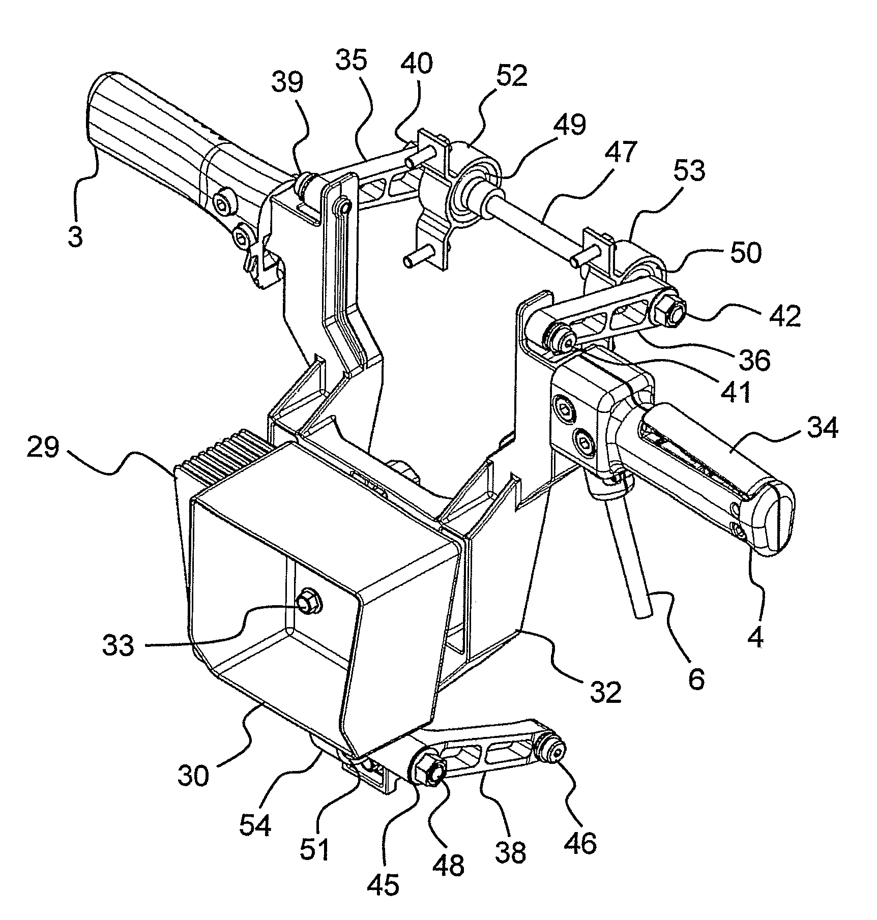
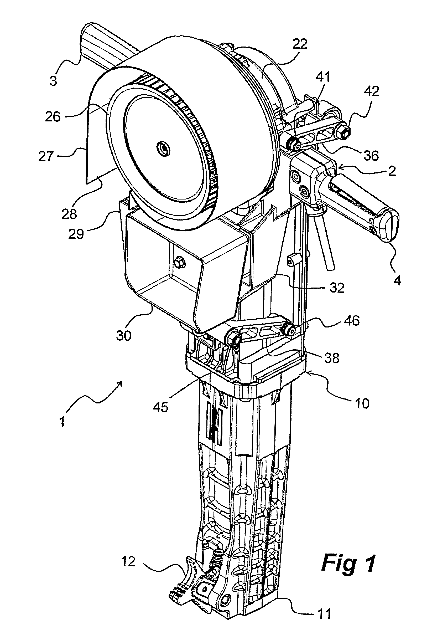
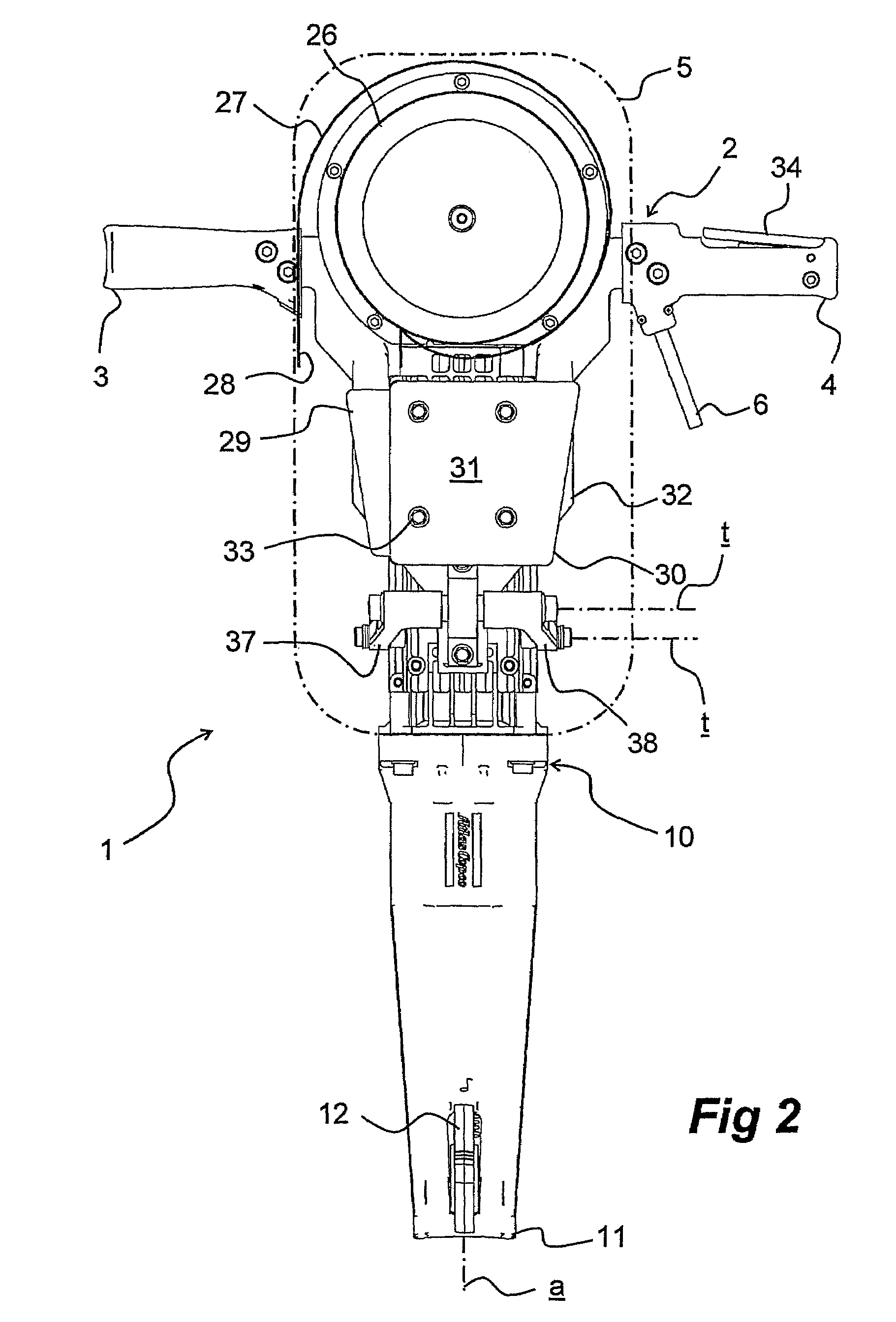
[0020]Initially, it is to be pointed out that for the breaker tool 1 illustrated in the drawings, including handle device 2, the same reference numbers are used, but for the sake of clarity not all details are pointed out in all figures. Further, it is to be observed that expressions like at the front, right or below are based on the normal use of the breaker tool 1. In that position the operator stands behind the breaker tool 1 with his right hand on a handle 3 on the right hand side of the breaker tool 1, with his left hand on a handle 4 on the left hand side of the breaker tool 1 and with the working part of the breaker tool 1 directed downwards. Finally, it is to noted that of course the breaker tool 1 is intended for receiving a chisel in a known way, even though a chisel is not shown in the drawings. The chisel has a longitudinal axis defining a geometric tool axis a extending along the entire breaker tool 1. Finally, it is to be pointed out that during use of the breaker tool...


PUM


Abstract

A breaker tool has a chassis carrying a motor, an impact mechanism operating in a certain working direction, an enclosure rigidly connected to the chassis and surrounding at least the motor, and a handle device including two handles protruding from opposite sides of the enclosure and are vibration damped relative to the chassis via swing arms, where the swing arms are arranged to accomplish a flexible parallel movement providing coupling between the chassis and the handle device. The handle device includes a bridge to which the handles are secured. The swing arms are pivotally connected to the bridge via first pivots and to the chassis via second pivots, where at least one of the first and second pivots is a torsion pivot that provides a limited torsion damped oscillation of the bridge relative to the chassis in a direction substantially parallel with the working direction.

Description

[0001]This application is a U.S. National Phase Application under 35 USC 371 of International Application PCT / SE2006 / 000603 filed May 24, 2006.TECHNICAL FIELD[0002]The invention relates to a breaker tool that comprises a chassis and a motor mounted thereon, an impact mechanism driven by the motor and arranged to operate in a certain working direction, a enclosure which surrounds at least the motor, and a handle device comprising two handles protruding at opposite sides of the enclosure and being vibration damped relative to the chassis via swing arms, wherein the swing arms are arranged to accomplish a flexible connection for parallel movement between the chassis and the handle device.PRIOR ART[0003]A breaker tool according to the preamble is previously described in U.S. Pat. No. 4,673,043. One of the advantages with the breaker tool described in this publication is that the handle thanks to swing arms is well vibration damped as to movements originating from the impact work perform...

Claims


Application Information

Patent Timeline
Patent Type & Authority Patents(United States)
IPC IPC(8): B25D17/04
CPCB25D17/043B25D17/24B25F5/006
Inventor BRAM, ERNST ARNE JOHANGUSTAVSSON, MAGNUS LIEBERT
Owner ATLAS COPCO AIRPOWER NV
Why Eureka
Try Eureka