Device for diversion of cavitation flowback

a flowback and cavitation technology, applied in mechanical equipment, transportation and packaging, wellbore/well accessories, etc., can solve the problems of substantial airborne particulates, unsuitable restriction of discharge flow, and substantial safety hazards, so as to reduce or prevent flowback particulates and facilitate replacement

Active Publication Date: 2010-01-05
ANTELOPE DEV
View PDF1 Cites 0 Cited by
  • Summary
  • Abstract
  • Description
  • Claims
  • Application Information

AI Technical Summary

Benefits of technology

[0005]The present invention provides a diverter to dissipate the energy of the “flowback” to allow for controlling and directing the materials, reducing airborne dust and contamination of the well site and surrounding area and, reduce or redirecting the noise generated by the flowback discharge. These goals are achieved using a structure which is self cleaning, thereby insuring the effectiveness of the cavitation process by minimizing any restriction or limitation of the volume of the discharge flow.
[0014]It is another object of the present invention to provide a flowback diverter which reduces or prevents flowback particulates from becoming airborne.

Problems solved by technology

If not controlled and / or directed, this discharge, or “flowback” can be a substantial safety hazard, create substantial quantities of airborne particulates, and contamination of the well site and / or surrounding area with settled particulates, mud, produced water and other such contaminants.
However for the cavitation procedure to be effective, it is not desirable to restrict the discharge flow.
Prior methods of containing flowback which have proven less than ideal include directing the flowback stream at an earthen berm or directing the stream through a baffled pipe.
The former method is largely ineffective at preventing airborne particulates and the latter can be complicated by the discharge by becoming blocked or clogged by the solid material in the flowback.
This self-cleaning effect increases the effectiveness of the cavitation process and reduces the possibility of a potentially dangerous sudden buildup of pressure in the lines or fittings feeding the diverter and any catastrophic failure which might result.

Method used


Image

  • Device for diversion of cavitation flowback
  • Device for diversion of cavitation flowback
  • Device for diversion of cavitation flowback

Examples


Embodiment Construction

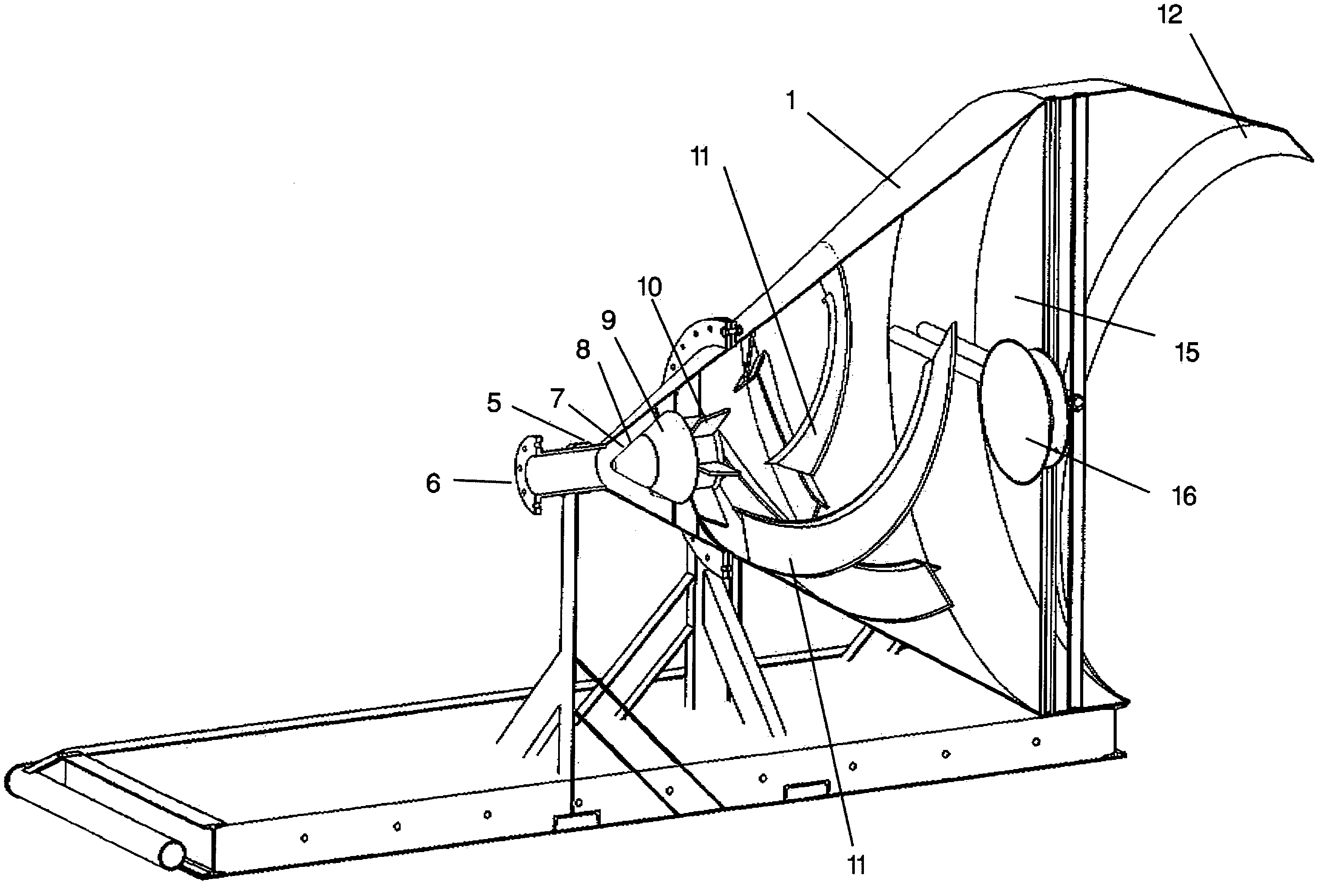
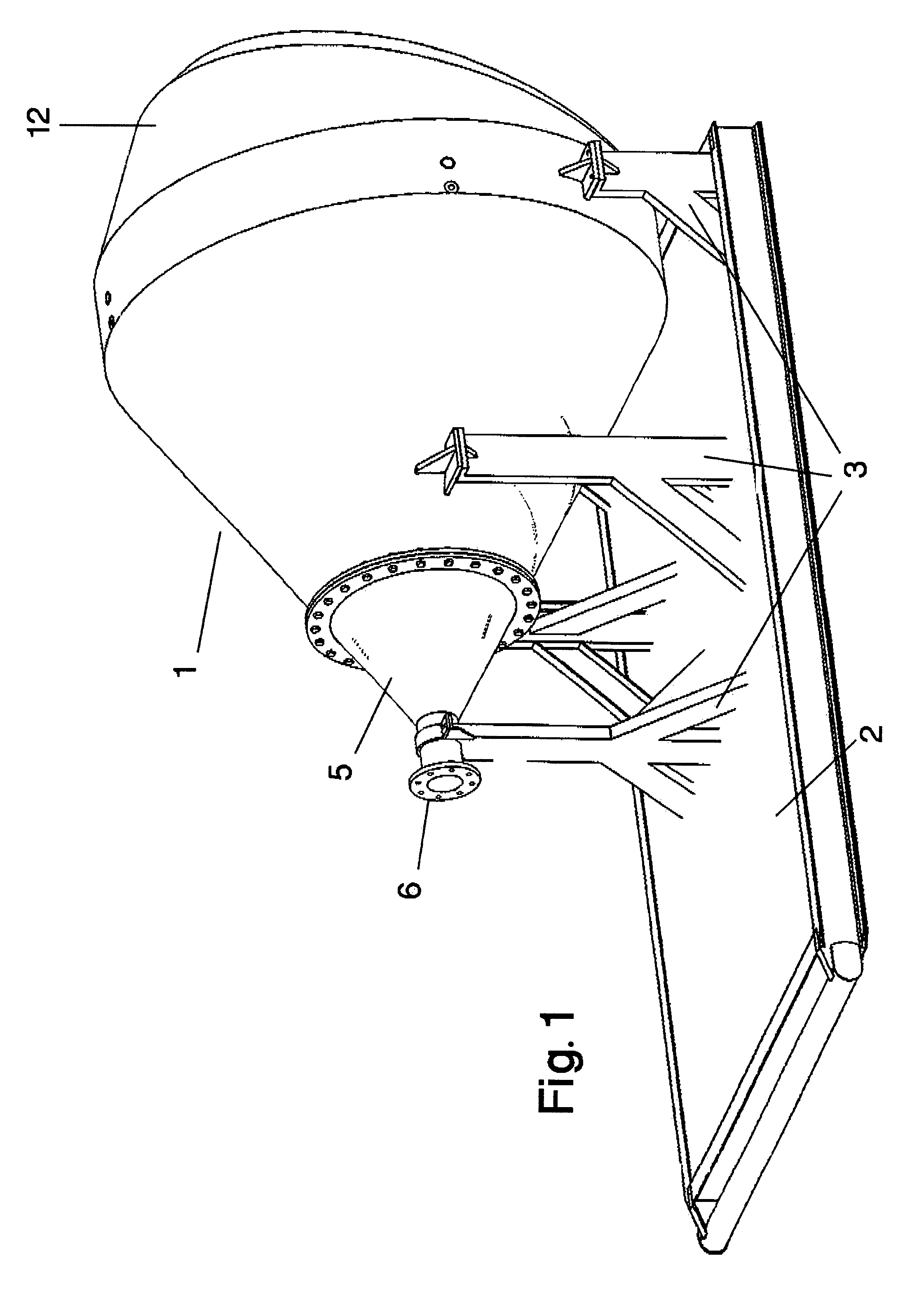
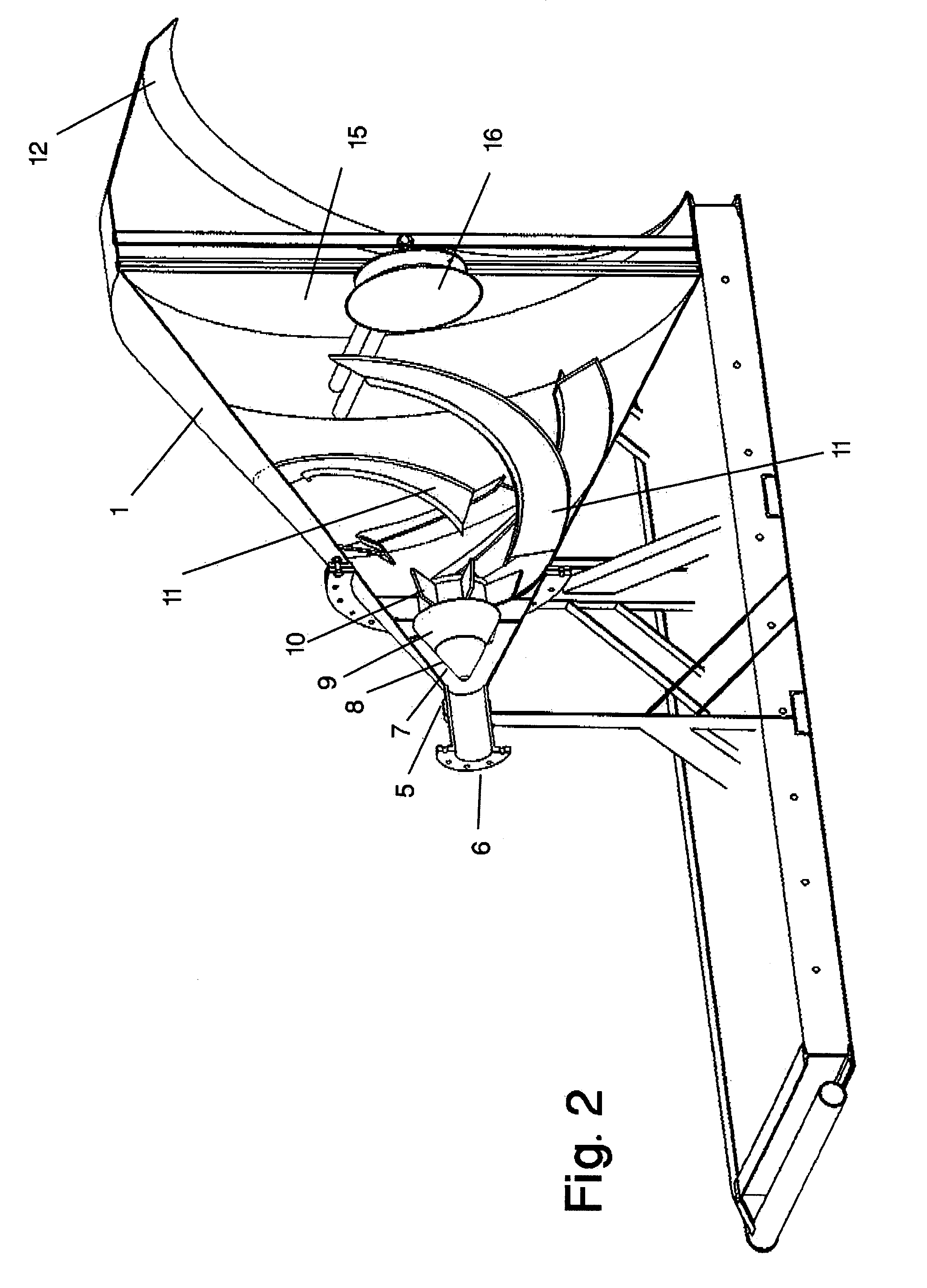
[0019]As shown in FIG. 1 the hollow conical containment shell 1 of the preferred embodiment is a heavy steel structure mounted on a base comprising a steel skid 2 approximately 8 feet wide and 14 feet long filled with concrete. Such a skid provides sufficient mass to resist the substantial reactive forces incurred during operation of the device without requiring the device to be permanently fixed at an operating site and allows transport of the device using normal heavy equipment. The shell is supported above and attached to the skid by suitable steel framing members 3. Flowback from a well is fed to the inlet portion 5 of the device through piping, typically steel pipe of six inch diameter, attached to inlet portion 5 using a normal flanged pipe fitting 6. The flow enters the smaller inlet end of the containment shell along the axis of the conical end shell and is directed against a conical diverter assembly 7 comprised of a solid faced central nose piece 8 mounted within and exten...


PUM


Abstract

A diverter for containing and reducing the velocity of the particulate discharge from a well bore being subjected to the process of “cavitation.” The diverter has a generally conical hollow containment shell and an internal diverter assembly with replaceable wear parts wherein the flow is directed into a spiral path along the inner surface of the containment shell. The path of flow is such that the flow velocity is dissipated without impeding or obstructing the flow of particulates. Water can be injected into the flow to help prevent fine particulates from becoming airborne.

Description

PRIOR APPLICATIONS[0001]This application is a based upon applicant's provisional patent application, 60 / 788,460 filed Mar. 31, 2006 which is hereby incorporated herein by reference.BACKGROUND OF THE INVENTION[0002]The present invention provides for diverting, containing and reducing the velocity of the discharge from a well bore being subjected to the process of “cavitation” as used to enhance production of coalbed methane.SUMMARY OF THE INVENTION[0003]Modern exploitation of fossil fuel energy resources has found an increasing source of natural gas in the extraction of coal bed methane, a byproduct of the coal formation process. Such methane can be recovered from coalbed deposits that are too deep to mine. A commonly used technique to enhance the recovery of methane from an underground coalbed deposit is known as “cavitation.” To extract the methane, a well is drilled into the coal seam. A tubing string is run into the well bore hole and air, carbon dioxide or other suitable gas is ...

Claims


Application Information

Patent Timeline
Patent Type & Authority Patents(United States)
IPC IPC(8): B05B1/26
CPCE21B43/006E21B43/34Y10T137/2087
Inventor KEITH, JAMES P.
Owner ANTELOPE DEV
Why Eureka
Try Eureka