Control input device with vibrating function
a technology of input device and function, which is applied in the direction of instruments, surveying and navigation, navigation instruments, etc., can solve the problems of operator inability to look at the display screen for safety reasons, and cannot recognize the degree of forwarding of playback objects
- Summary
- Abstract
- Description
- Claims
- Application Information
AI Technical Summary
Benefits of technology
Problems solved by technology
Method used
Image
Examples
first embodiment
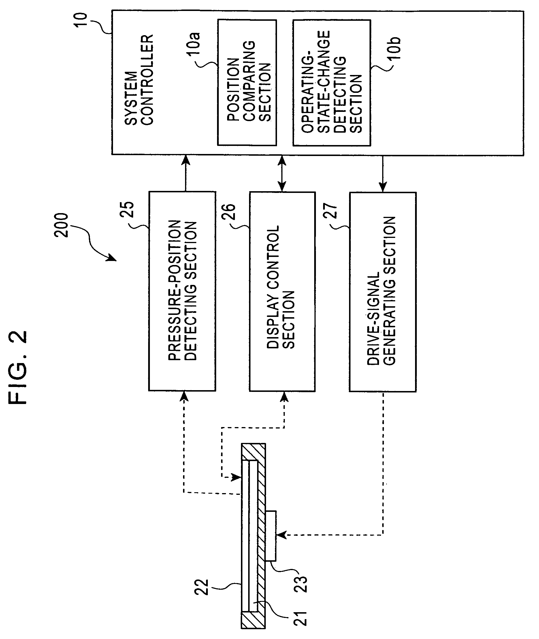
[0047]FIG. 2 is a functional block diagram of a control input system 200 with a vibration function according to a first embodiment of the invention.
[0048]As shown in FIG. 2, the vibration-function-equipped control input system 200 includes a pressure-position detecting section 25 that produces a detection signal depending on the position of the touch panel 22 pressed; a display control section 26 that allows the liquid-crystal panel 21 to display a control screen and obtains the position of a control key displayed on the control screen; and a drive-signal generating section 27 that generates vibration to be applied to the vibration unit 23.
[0049]The system controller 10 includes a position comparing section 10a that compares the position of the touch panel 22 pressed to the position of a control key displayed on the liquid-crystal panel 21; and an operating-state-change detecting section 10b that detects the change of music or the like to be controlled.
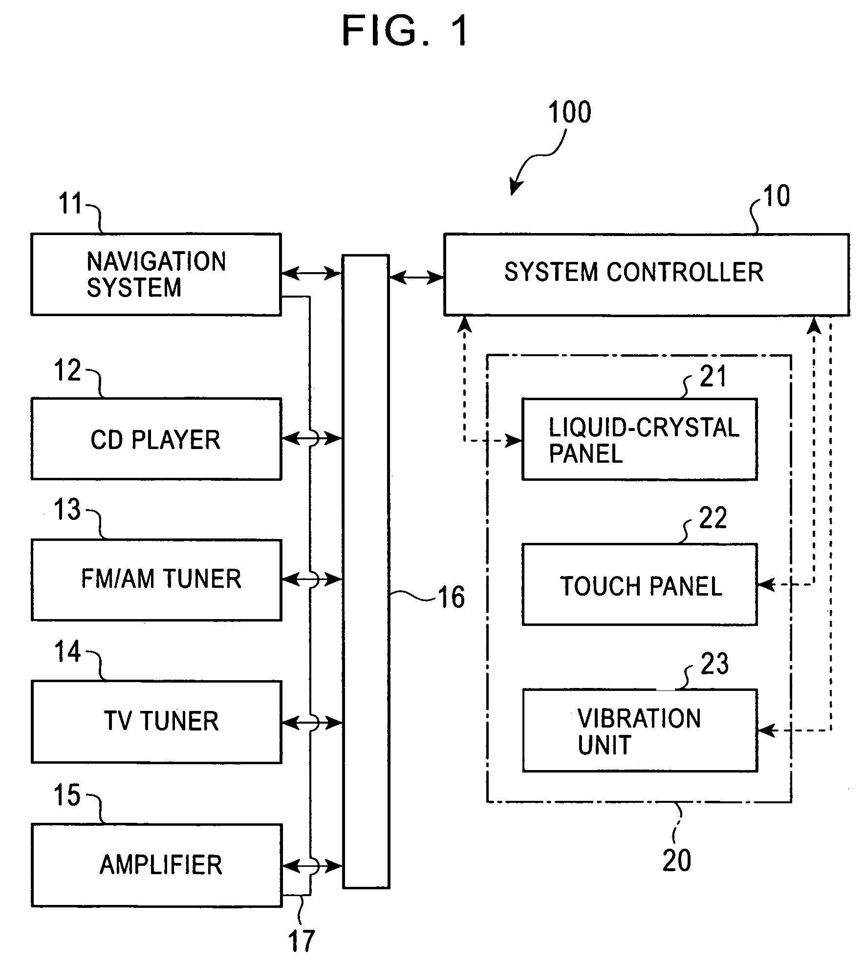
[0050]The display unit 20 has ...
second embodiment
[0087]A vibration-function-equipped control input system 200a according to a second embodiment of the invention will be described hereinbelow.
[0088]The second embodiment is different from the first embodiment in that the control object is a finite value that varies gradually and has a reference point being a higher limit, a lower limit, or a median. When the sound level has passed through the reference point, the touch panel is vibrated.
[0089]FIG. 7 is a functional block diagram of a vibration-function-equipped control input system 200a according to the second embodiment. This embodiment is also an application of the invention to the car-mounted navigation and AV system 100. The difference between the second embodiment and the first embodiment is that a system controller 10A has a reference-point-passage detecting section (control section) 10c. The other structure and operation (function) are basically the same as those of the first embodiment. Accordingly, the same components in FI...
third embodiment
[0115]A vibration-function-equipped control input system 200b according to a third embodiment of the invention will be described hereinbelow.
[0116]The third embodiment is different from the first and second embodiments in that the control object is field intensity when receiving FM broadcasting and so on; and the touch panel is vibrated when the field intensity has reached a predefined value.
[0117]FIG. 11 is a functional block diagram of a vibration-function-equipped control input system 200b according to the third embodiment. This embodiment is also an application of the invention to the car-mounted navigation and AV system 100. The difference between this embodiment and the first and second embodiments is that a system controller 10B has a field-intensity detecting section (control section) 10d. The other structure and operation (functions) are basically the same as those of the first embodiment. Accordingly, the same components in FIG. 10 as those of FIG. 2 are given the same ref...
PUM
 Abstract
Description
Claims
Application Information
 - R&D
- Intellectual Property
- Life Sciences
- Materials
- Tech Scout
- Unparalleled Data Quality
- Higher Quality Content
- 60% Fewer Hallucinations
Browse by: Latest US Patents, China's latest patents, Technical Efficacy Thesaurus, Application Domain, Technology Topic, Popular Technical Reports.
© 2025 PatSnap. All rights reserved.Legal|Privacy policy|Modern Slavery Act Transparency Statement|Sitemap|About US| Contact US: help@patsnap.com


