
Combat shirt and armor system

a technology of armor system and combat shirt, applied in chemical protection, nuclear engineering, nuclear elements, etc., can solve the problems of shirt shape loss and increased perspiration, and achieve the effect of reducing garment distortion

Active Publication Date: 2009-12-29
LINEWEIGHT
View PDF49 Cites 43 Cited by
  • Summary
  • Abstract
  • Description
  • Claims
  • Application Information

AI Technical Summary

Benefits of technology

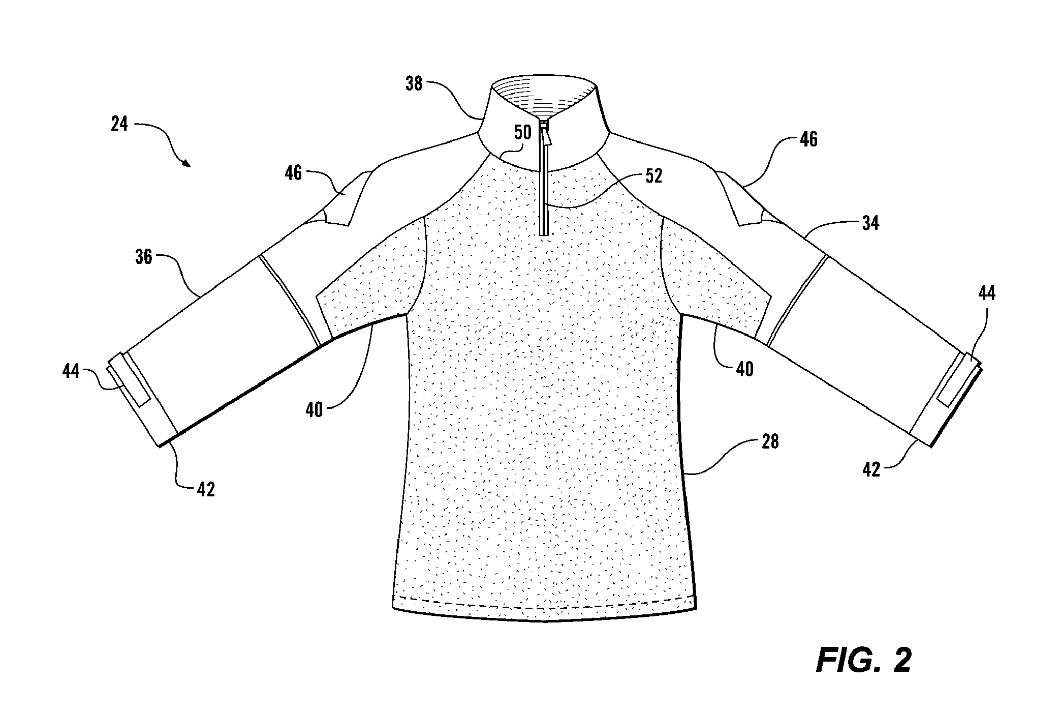
[0006]A protective body armor system for protection against ballistic threats of this invention has an armored element such as a vest with front and rear ballistic armor. A long-sleeved shirt is worn beneath the ballistic armor which has a wicking, lightweight, low thermal insulation torso element. Two long sleeves are connected to and extend from the torso element. The shirt has a durable collar connected to the torso element and to the two sleeves. The collar extends upwardly from the armored element. The collar is less stretchy than the torso element, and serves to connect the two sleeves and to restrain the garment from undesired distortion. The torso element is substantially overlain by portions of the armored element, while the collar and portions of the sleeve extend beyond the armored element. The collar and sleeves are formed of a more durable material than the torso element.
[0007]It is an object of this invention to provide a body armor system having a base layer shirt which has different wicking and durability properties under armored and unarmored regions, and which resists undesired distortion.

Problems solved by technology

Higher metabolic activities encountered under combat conditions can result in greater perspiration.
However, the wicking material is also more elastic or stretchable than the durable fabric, with the result that the shirt tends to lose its shape, with the durable sleeves pulling down the resilient torso material at the shoulders.

Method used


Image

  • Combat shirt and armor system
  • Combat shirt and armor system
  • Combat shirt and armor system

Examples


Embodiment Construction

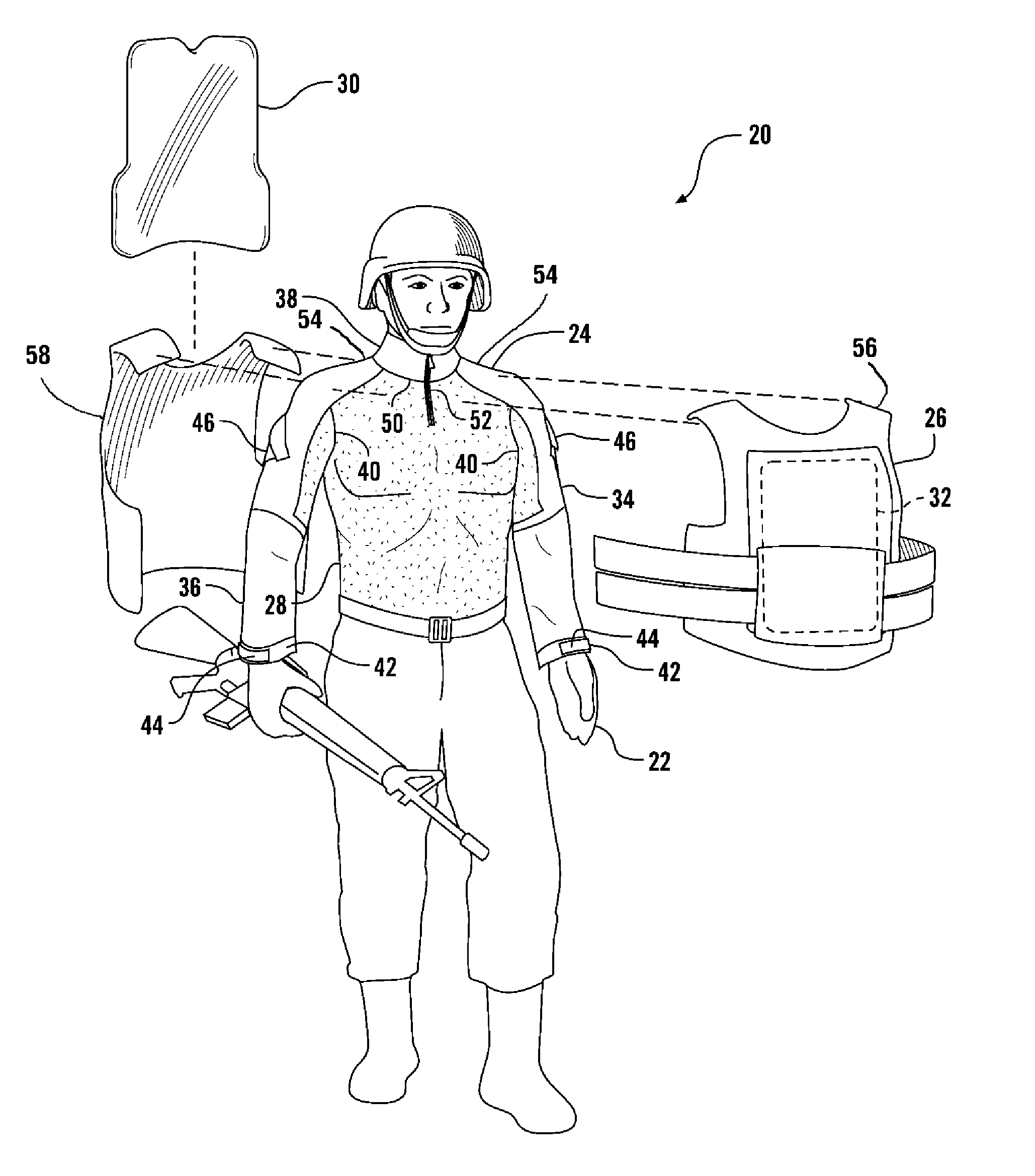
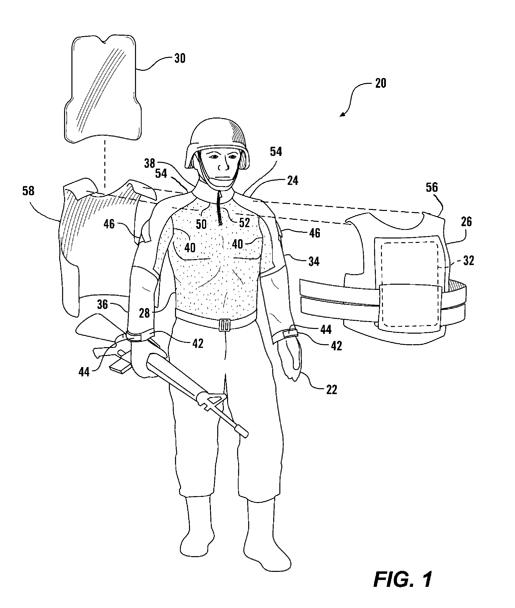
[0012]Referring more particularly to FIGS. 1-3, wherein like numbers refer to similar parts, a body armor system 20 of this invention is shown in relation to a wearer 22 in FIG. 1. The wearer 22 will typically be a soldier or police officer performing duties which present a risk of encountering gunfire. Such duties not infrequently call for high levels of exertion while carrying equipment. The armor system 20 is comprised of a shirt 24 worn with an armored element 26. The armored element 26 may be a ballistic vest such as is disclosed in our U.S. Pat. No. 6,892,392, the disclosure of which is incorporated by reference herein, or it may be any conventional ballistic vest, for example the U.S. Military Interceptor Multi-Threat Body Armor System, or its predecessor the Personnel Armor System for Ground Troops (PASGT) vest. The vest may have soft armor 30 or plate armor 32 inserts. The vest has a front section 56 with the armor 32, and a rear section 58 with the armor 30.

[0013]The shirt...


PUM


Abstract

A protective body armor system for protection against ballistic threats has an armored element such as a vest with front and rear ballistic armor. A long-sleeved shirt is worn beneath the ballistic armor which has a wicking, lightweight, low thermal insulation torso element. Two long sleeves are connected to and extend from the torso element. The torso element is substantially overlain by portions of the armor element, while portions of the sleeve extend beyond the armored element. The shirt has a durable collar connected to the torso element and to the two sleeves. The collar extends upwardly from the armored element. The collar is less resilient than the torso element, and serves to connect the two sleeves and to restrain the garment from undesired distortion.

Description

BACKGROUND OF THE INVENTION[0001]The present invention relates to ballistic protective apparel in general, and more particularly to undergarments for use with ballistic armor.[0002]Persons exposed to projectile threats, such as police officers and soldiers, may seek a certain level of protection by wearing armored clothing. Low velocity projectiles such as handgun rounds, fragmentation rounds from a grenade or mortar, and miscellaneous shrapnel may be countered by so-called “soft armor.” Soft armor is worn in the form of jackets, vests, etc. which are composed of assemblies of ballistic fabric such as those formed from DuPont Kevlar® fibers. In a more serious threat situations, where higher velocity rifle rounds must be countered, soft armor has typically been supplemented with hard armor. The hard armor is fabricated of rigid plates of ceramic, polymer, or metal. A common approach to mounting the plates to the wearer is to secure them within exterior pockets fabricated on a soft ar...

Claims


Application Information

Patent Timeline
Patent Type & Authority Patents(United States)
IPC IPC(8): F41H1/00F41H1/02G21F3/02
CPCF41H1/02A41B9/06A41D2400/60A41D31/12
Inventor CRYE, CALEB CLARKFEHLBERG, ERIC OWENTHOMPSON, GREGG M.
Owner LINEWEIGHT
Learn More