
Actuator controller for monitoring health and status of the actuator and/or other equipment

a technology for actuators and controllers, applied in the field of digital valve controllers, can solve the problems of not being scalable, not configurable, not typically providing event logging, and current valve controllers not typically providing remote monitoring and control capability

Inactive Publication Date: 2009-12-22
CURTISS WRIGHT FLOW CONTROL CORP
View PDF20 Cites 47 Cited by
  • Summary
  • Abstract
  • Description
  • Claims
  • Application Information

AI Technical Summary

Benefits of technology

"The patent describes a device for controlling an actuator in an explosion-proof housing. The device has two controllers: a primary controller and a backup controller. The primary controller is sealed within the housing and is responsible for controlling the actuator's functions. The backup controller is mounted within the housing and can take control in case of failure of the primary controller. The device also has an operator interface with a display for accepting operator settings and a memory for storing expected parameters of the actuator. The device can communicate with a remote terminal for viewing and controlling the actuator. The invention allows for monitoring and recording of events and faults, providing valuable information to operators."

Problems solved by technology

Such controllers do not typically provide event logging, are not configurable, are not programmable, and are not scalable.
Furthermore, current valve controllers do not typically provide remote monitoring and control capability, don not properly support customer troubleshooting and training, don't adequately support automated health monitoring, diagnostics, and testing, and don't provide predictive maintenance.
Current controllers aren't adequately customizable by either the customer or the vendor, and they do not adequately support easy setup.

Method used


Image

  • Actuator controller for monitoring health and status of the actuator and/or other equipment
  • Actuator controller for monitoring health and status of the actuator and/or other equipment
  • Actuator controller for monitoring health and status of the actuator and/or other equipment

Examples


Embodiment Construction

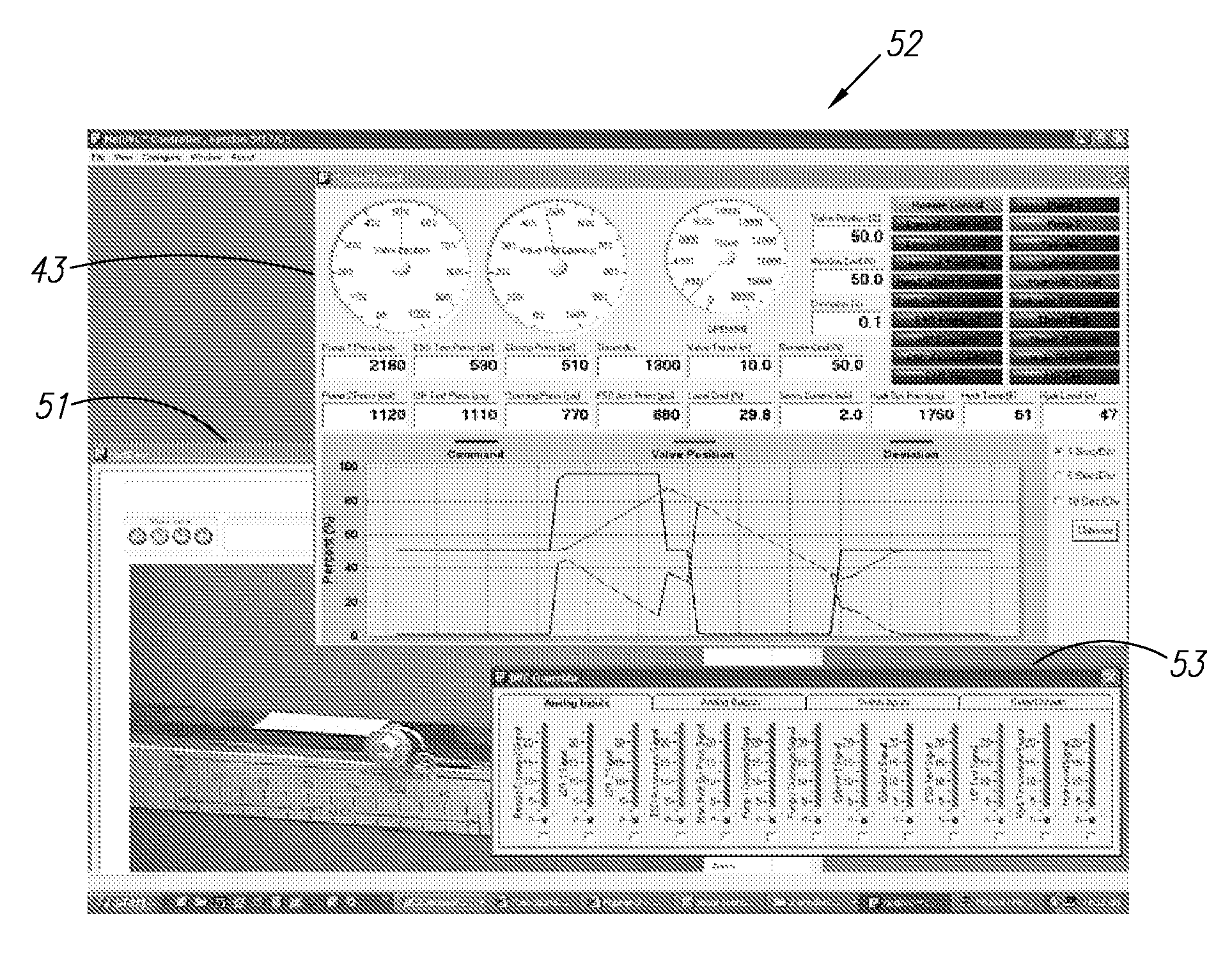
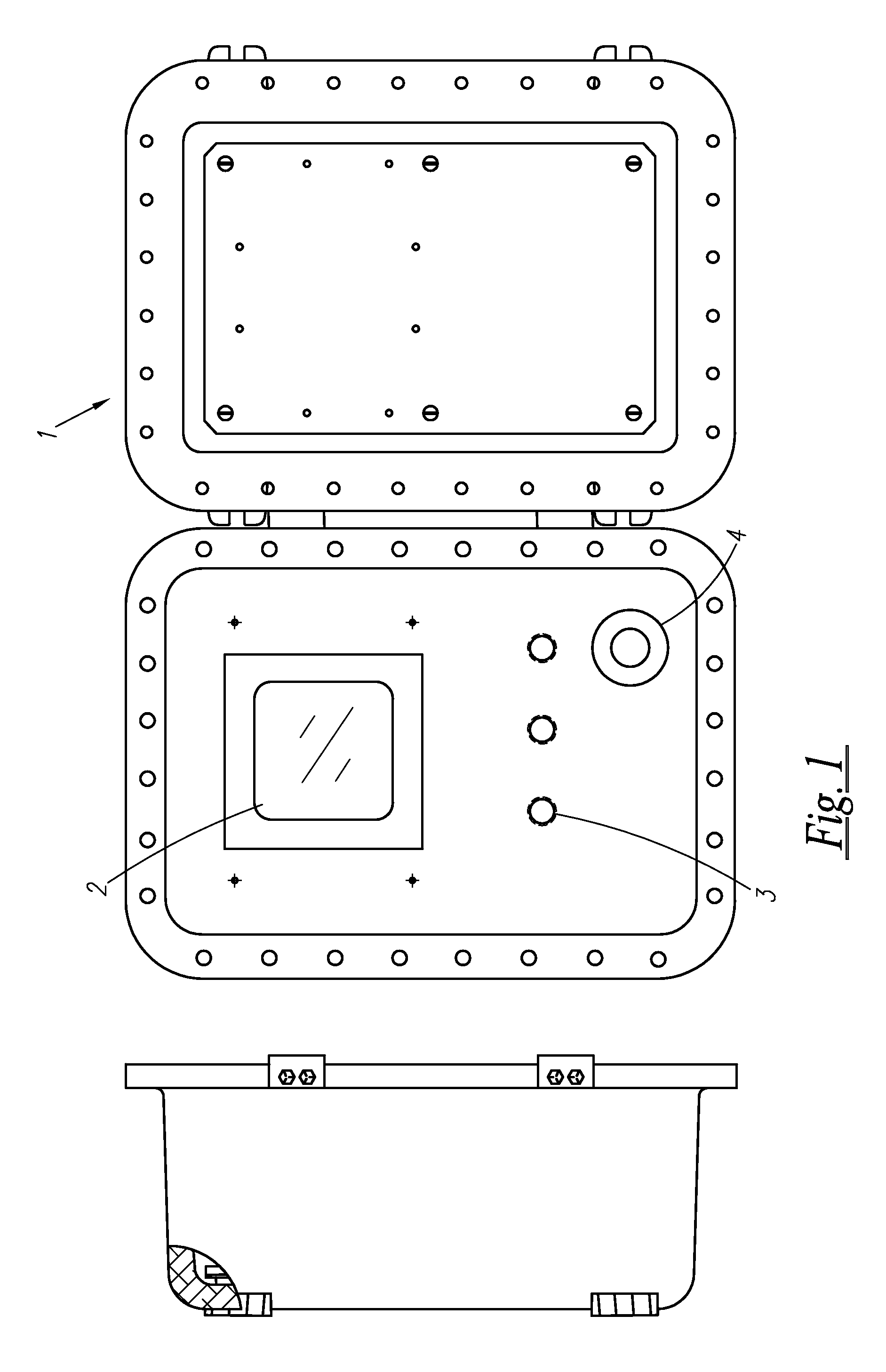
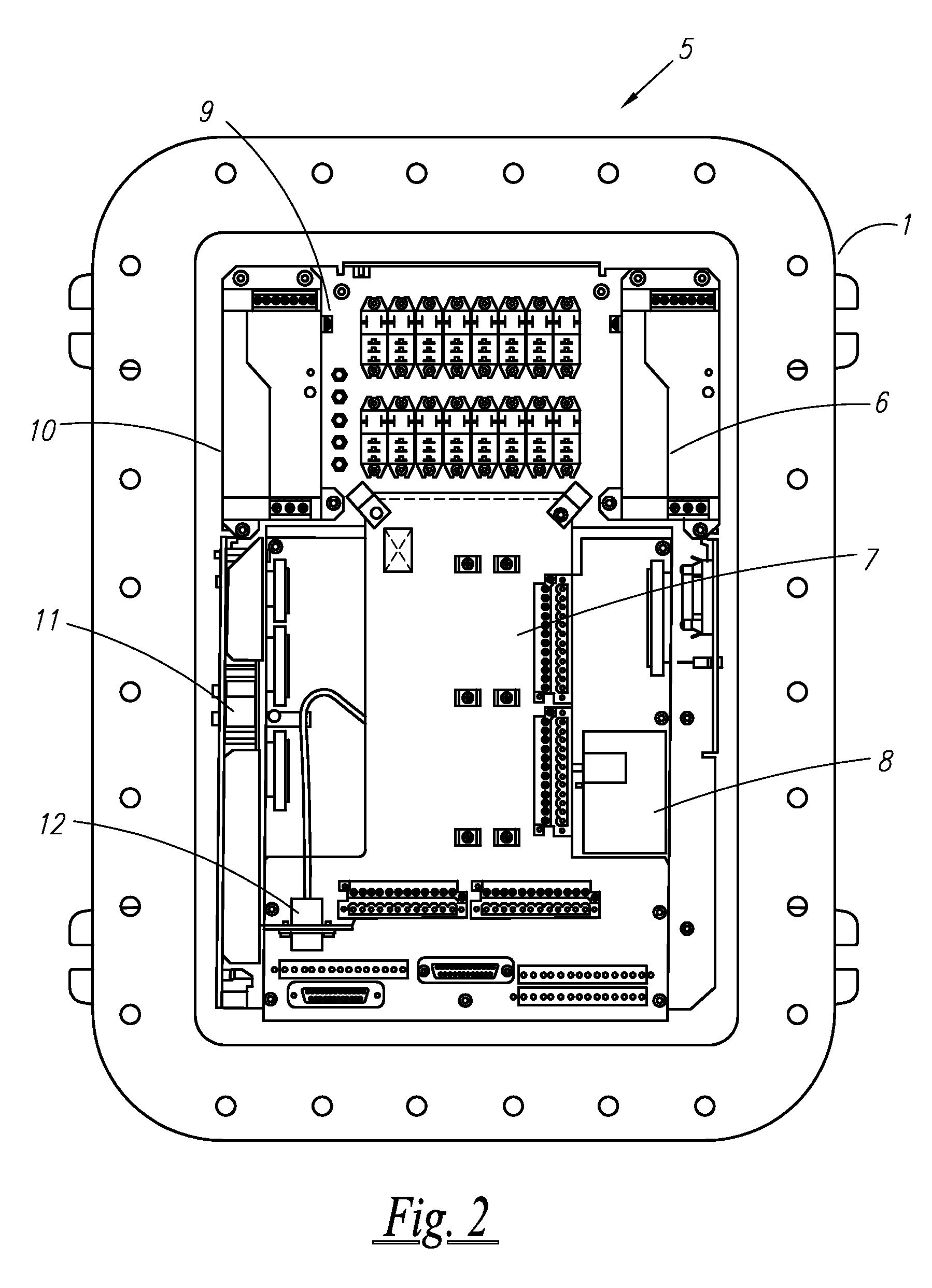
[0032]Provided is a Digital Valve Controller (DVC) for supporting various valve applications (e.g. plug and slide valves, among others). Note that is this description, a “controller” component may include various controller and processor devices. These are basically programmable components, which may, or may not, be discrete, that are utilized for receiving various inputs for processing, and providing various outputs to control various devices, and a “controller”, as used in this document, may include a “processor”, where appropriate.

[0033]The DVC is housed in an enclosure or a case, such as an explosion-proof case, for example. FIG. 1 is a drawing of an embodiment of a DVC front panel and explosion-proof case 1 according to an example embodiment. A 5.5 inch color, quarter VGA display 2 provides a friendly “WINDOWS-like” Graphical User Interface (GUI). In an example embodiment, the display 2 is mounted to the inside cover of the explosion-proof case 1. The DVC GUI can be set to disp...


PUM


Abstract

A device for controlling an actuator includes a controller mounted within a housing having an outer surface. The controller is adapted for controlling outputs connected to the actuator for controlling an operation of the actuator. A data input interface receives data from the actuator and / or from other equipment being acted on by the actuator. A memory stores expected parameters of the actuator. An operator interface provided on the housing's outer surface accepts operator commands and / or settings for input to the controller. A display and / or indicator on the housing's outer surface displays an output of the controller. The controller compares the data, and / or derived parameters of the data, with the expected parameters, to monitor a health and status of one or both of the actuator and the other equipment. The controller indicates the health and the status to the operator utilizing the display and / or indicator.

Description

CROSS-REFERENCE TO RELATED APPLICATIONS[0001]Benefit of U.S. Provisional Patent Application Ser. No. 60 / 696,115, filed Jul. 1, 2005, is hereby claimed and the disclosure incorporated herein by reference.[0002]The disclosure of this patent document contains material which is subject to copyright protection. The copyright owner has no objection to the facsimile reproduction by anyone of the patent document or the patent disclosure, as it appears in the Patent and Trademark Office patent file or records, but otherwise reserves all copyright rights whatsoever.BACKGROUND OF THE INVENTION[0003]The present invention relates to valve controllers, and more particularly to digital valve controllers for controlling valves and / or valve actuators.[0004]Conventional approaches for controlling valves typically involve analog valve controllers. Such controllers do not typically provide event logging, are not configurable, are not programmable, and are not scalable.[0005]Furthermore, current valve c...

Claims


Application Information

Patent Timeline
Patent Type & Authority Patents(United States)
IPC IPC(8): G05D11/00G05D7/00
CPCG05B9/02G05B2219/24028G01R31/2829
Inventor BORAH, FREDERIC M.GAVARIAN, RICHARD J.LEIB, JR., ANTHONYVENABLE, JAMES
Owner CURTISS WRIGHT FLOW CONTROL CORP
Learn More