
Fuser apparatus, image forming apparatus including the fuser apparatus, and fuser controlling method

a technology of fuser and fuser roller, which is applied in the direction of electrographic process apparatus, instruments, optics, etc., can solve the problems of inability to shorten the replacement cycle of components, the fuser roller is prone to deformation during use, and the fuser roller is prone to deformation, etc., to achieve the effect of improving the efficiency of the fuser, suppressing the temperature overshoot, and prolonging the service life of the fuser roller

Inactive Publication Date: 2009-12-22
SHARP KK
View PDF6 Cites 4 Cited by
  • Summary
  • Abstract
  • Description
  • Claims
  • Application Information

AI Technical Summary

Benefits of technology

This solution effectively suppresses temperature overshoot, prolongs the service life of fuser components, and improves the efficiency of the image forming process by maintaining consistent temperatures and reducing heat-related stress on the fuser rollers.

Problems solved by technology

The receptacle has a limited power supply capacity.
Further, components of the fuser are liable to be degraded during use in a higher temperature environment and, therefore, replaced after their service lives.
However, it is impermissible to shorten the cycle of the replacement of the components for increasing the processing speed of the image forming apparatus.
The fuser to be provided in the high speed image forming apparatus shares the power supply with the peripheral devices and, therefore, suffers from limitations of an office or domestic supply voltage and a breaker current capacity.
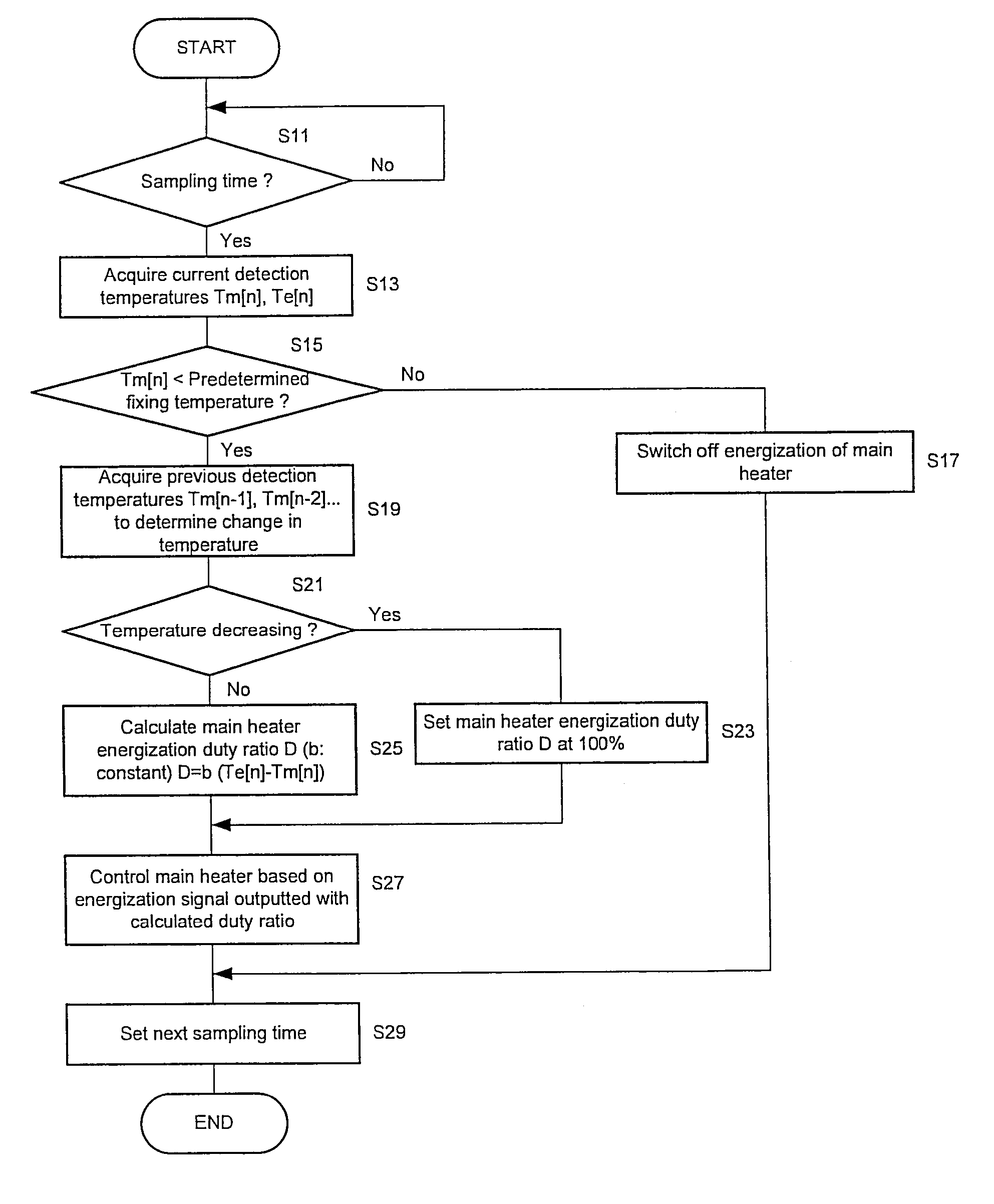
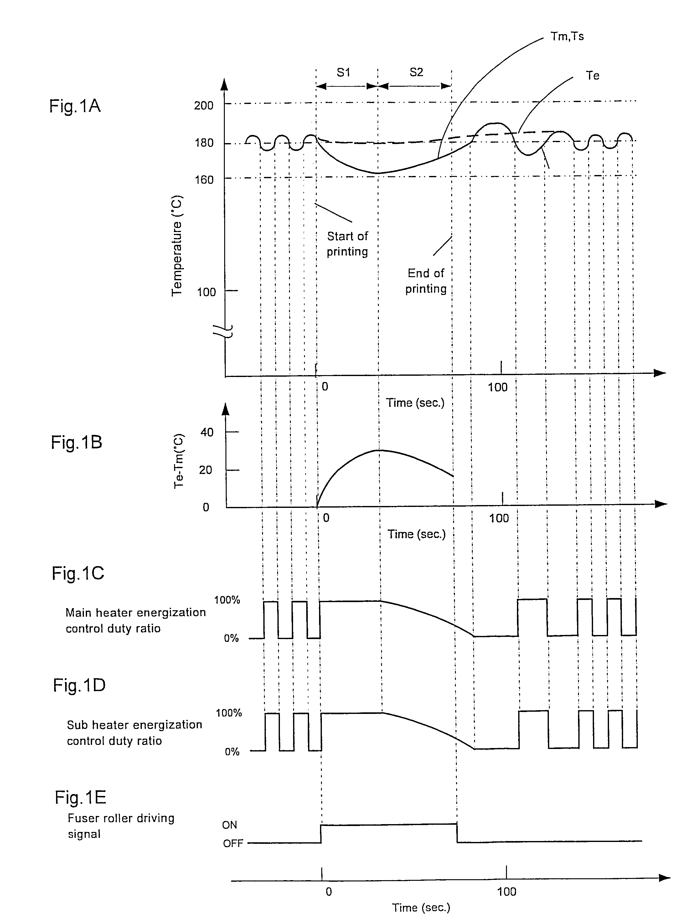
In this controlling method, the heat roller suffers from significant temperature overshoot in a standby state immediately after the end of the printing process.
This reduces the service life of the heater roller (fuser roller).
That is, the temperature overshoot significantly thermally deteriorates the roller, adversely affecting the durability of the roller.
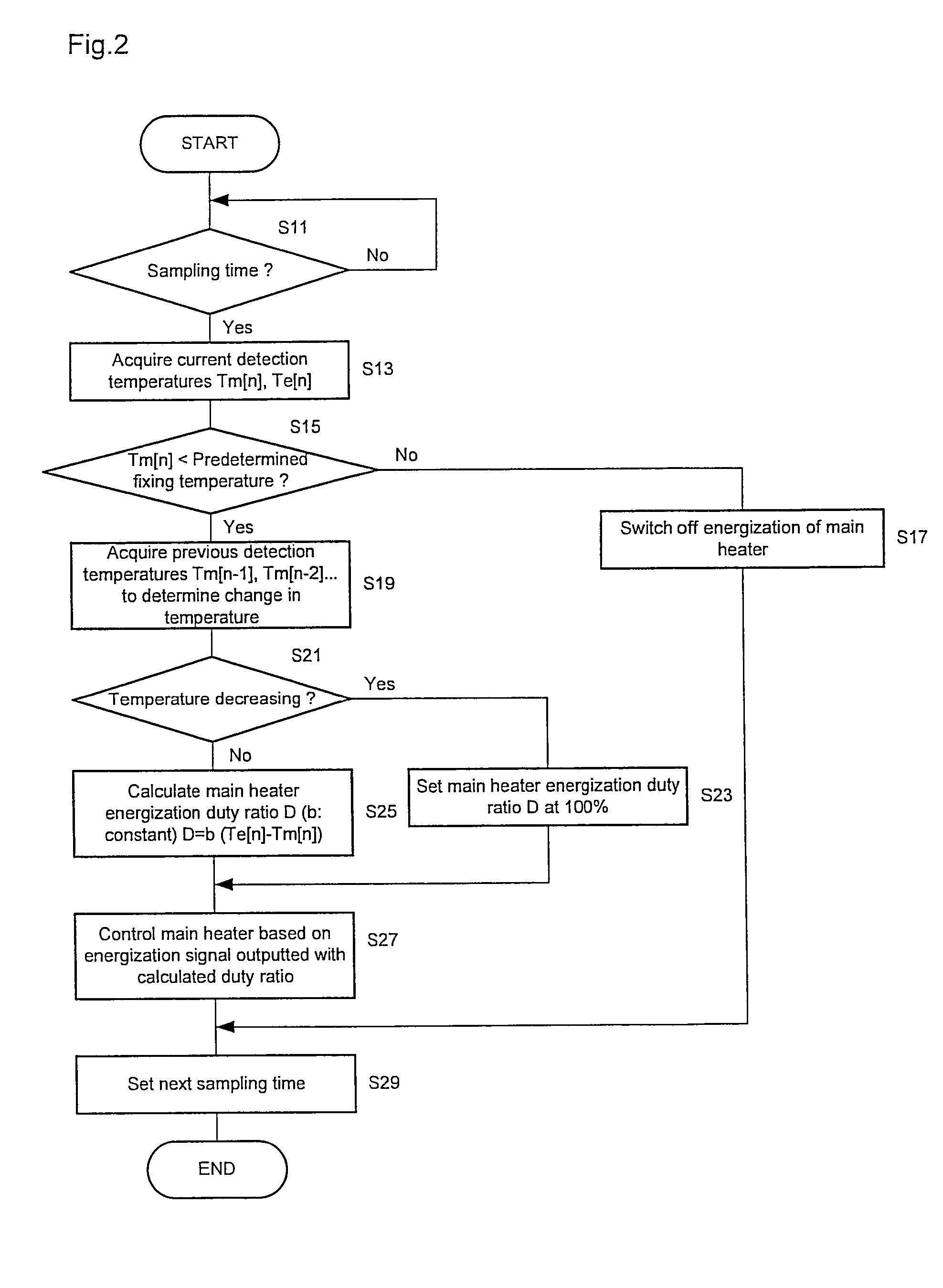
Even if the heater is turned on upon detection of the temperature reduction of the fuser member, the fuser member suffers from a response delay because it has a heat capacity.
However, the temperature of the fuser member continues to increase due to the response delay attributable to the heat capacity of the fuser member, resulting in the temperature overshoot.
During the fixing operation, it is tough for the components of the fuser member to withstand the temperature change in the high temperature range.
If the contact surface temperature of the fuser roller is excessively increased due to the temperature overshoot, deterioration of the components of the roller is accelerated.
However, it is difficult to eliminate the delay in the response to the detection of the temperature attributable to the heat capacity of the fuser roller.

Method used


Image

  • Fuser apparatus, image forming apparatus including the fuser apparatus, and fuser controlling method
  • Fuser apparatus, image forming apparatus including the fuser apparatus, and fuser controlling method
  • Fuser apparatus, image forming apparatus including the fuser apparatus, and fuser controlling method

Examples


Embodiment Construction

[0034]In the aforementiond fuser apparatus mentioned in the item (1), the energization controlling member may control the energization power by turning on and off energization of the heating member and varying a ratio between an on-period and an off-period.

[0035]In the fuser apparatus, the fuser member may be a fuser roller. Alternatively, the fuser member may be a fuser belt.

[0036]In the fuser apparatus, the heating member may be a heater disposed in generally center portion of an axis of a fuser roller serving as the fuser member. Alternatively, the heating member may be a heater disposed in opposed relation to a surface of the fuser belt for heating the fuser belt, or a heater disposed in a fuser belt driving roller for heating the fuser belt via the roller.

[0037]In the fuser apparatus, the fuser member may be a fuser roller which has a peripheral surface having a greater width than a width of the recording medium in the axis direction, the contact surface may be a generally axia...


PUM


Abstract

A fuser apparatus including: a fuser member having an endless contact surface to be brought into contact with each of successively transported recording media and a non-contact surface and being arranged to apply heat to the recording medium from the contact surface to fix a toner on the recording medium; a heating member energized to supply heat to the contact surface; a contact surface temperature detecting member for detecting a temperature of the contact surface; a non-contact surface temperature detecting member for detecting a temperature of the non-contact surface; and an energization controlling member for controling energization power of the heating member; wherein the energization controlling member controls the heating member energization power so that the heating member energization power is reduced as a difference between the non-contact surface temperature and the contact surface temperature decreases.

Description

CROSS-REFERENCE TO RELATED APPLICATION[0001]This application is related to Japanese application No. 2005-356576 filed on Dec. 9, 2005 whose priority is claimed under 35 USC §119, the disclosure of which is incorporated by reference in its entirety.BACKGROUND OF THE INVENTION[0002]1. Field of the Invention[0003]The present invention relates to a fuser apparatus, an image forming apparatus including the fuser apparatus, and a fuser controlling method.[0004]2. Description of the Related Art[0005]Since the processing speeds of image forming apparatuses have been increased in recent years, it is imperative to improve the efficiency and service life of a fuser apparatus (fuser).[0006]Such an image forming apparatus is generally supplied with electric power from a receptacle to which the apparatus is plugged in an office or the like. The receptacle has a limited power supply capacity. In Japan, for example, the receptacle has a rated voltage of 100V and a rated current of 15A. Therefore, t...

Claims


Application Information

Patent Timeline
Patent Type & Authority Patents(United States)
IPC IPC(8): G03G15/20
CPCG03G15/2042
Inventor NANBA, TOYOAKIIDE, ATSUSHITATEISHI, YOSHINOBU
Owner SHARP KK
Learn More