
System and method for testing worst case transients in a switching-mode power supply

a power supply and switching-mode technology, applied in the field of power converters, can solve the problems of shortening affecting the service life of the power supply, and affecting the operation so as to achieve the effect of reducing the number of transients produced, and reducing the service life of the power supply

Active Publication Date: 2009-12-15
NVIDIA CORP
View PDF11 Cites 5 Cited by
  • Summary
  • Abstract
  • Description
  • Claims
  • Application Information

AI Technical Summary

Benefits of technology

The present invention provides a method for testing the worst-case transients of a switching-mode power supply (SMPS) by monitoring a turn-on parameter of the top transistor and changing the state of the load being provided to the SMPS when the turn-on parameter indicates that the top transistor has turned off. The method allows for the testing of worst-case transients in a more reliable and accurate manner than prior art approaches.

Problems solved by technology

However, if the load suddenly changes (e.g., when a graphics card turns on or turns off), the output voltage may temporarily deviate from the constant value until the control circuit within the SMPS makes the adjustments necessary to return the output voltage to the desired constant value.
Such temporary excursions from the desired output voltage are commonly referred to as “transients.” As is well-known, large transients in the output voltage of an SMPS may negatively impact the load.
One drawback to the above approach, however, is that the detected transients above or below the desired output voltage may not be the largest transients produced within the SMPS.
Since prior art static load generators, such as the SLG 160, do not take into consideration the state of the power supply, testing the worst case transients with a testing system such as the testing system 100 is ultimately unreliable.

Method used


Image

  • System and method for testing worst case transients in a switching-mode power supply
  • System and method for testing worst case transients in a switching-mode power supply
  • System and method for testing worst case transients in a switching-mode power supply

Examples


Embodiment Construction

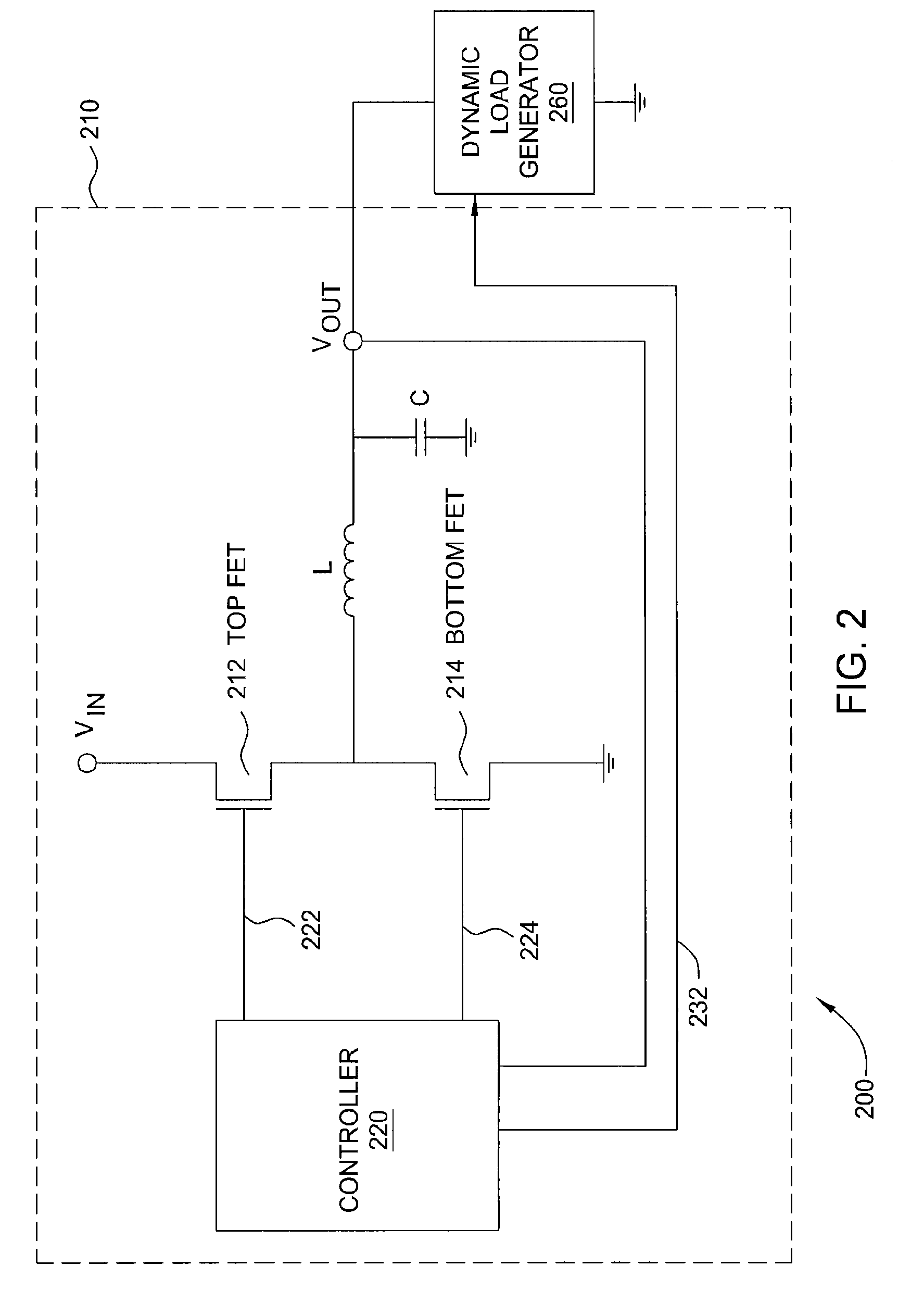
[0016]FIG. 2 illustrates a testing system 200 for testing the worst-case transient in output voltage that a switching-mode power supply will produce in the face of a varying load, according to one embodiment of the present invention. As shown, the testing system 200 includes a switching-mode power supply 210 connected to a dynamic load generator (DLG) 260. The SMPS 210 includes a top FET 212 and a bottom FET 214. Similar to FIG. 1, the top FET 212 and the bottom FET 214 are controlled by a controller 220 through connections 222 and 224, respectively. When the DLG 260 provides a constant load to the SMPS 210, the controller 220 ensures that an input voltage (shown as “Vin”), is converted into the desired output voltage (shown as “Vout”) by setting the duty cycle, frequency, and / or phase shift of the top FET 212 and the bottom FET 214 to appropriate values.

[0017]The controller 220 turns the top FET 212 and the bottom FET 214 on or off by turning their respective gate voltages on or of...


PUM


Abstract

One embodiment of the present invention sets forth a system and a method for testing the worst-case transients in the output voltage produced by a switching-mode power supply (SMPS). The system includes an SMPS and a dynamic load generator (DLG). The SMPS converts the input voltage into the output voltage by using a top field-effect transistor (FET) and a bottom FET. The worst case transients occur when the load being provided to the SMPS is turned on or off at the same time the top FET is turned off. The DLG is configured to monitor the edge of the gate voltage of the top FET and to turn the load provided to the SMPS on or off when the edge of the gate voltage of the top FET is falling. Consequently, the disclosed system is able to test the worst-case transients in the output voltage produced by the SMPS in a manner that is more reliable than prior art approaches.

Description

BACKGROUND OF THE INVENTION[0001]1. Field of the Invention[0002]Embodiments of the present invention generally relate to power converters and, more specifically, to systems and methods for testing worst case transients in a switching-mode power supply.[0003]2. Description of the Related Art[0004]Electric power is rarely used in electronic devices in the same form in which the power was originally produced or distributed. Therefore, a vast majority of electronic systems include some type of device that performs power conversions to convert power into a form that can be more readily used within those systems. One example of such a conversion device is a switching-mode power supply (SMPS). An SMPS incorporates a control circuit that switches transistors on and off in order to transfer electric energy from the source to the load through magnetic components and capacitors. A specific example of an SMPS is a switching DC-DC power supply that draws 100 Watts of power from a 48 Volt DC sour...

Claims


Application Information

Patent Timeline
Patent Type & Authority Patents(United States)
IPC IPC(8): G05F1/59
CPCH02M1/44H02M3/1588Y02B70/1466Y02B70/10
Inventor JACOBY, RAMBOD
Owner NVIDIA CORP
Learn More