
Compressed air filter assembly for nail gun

a filter assembly and compressor technology, applied in the direction of filtration separation, portability drilling machines, separation processes, etc., can solve the problems of reducing the filtration capacity of the filter, easy damp or deformation of the filter, and easy falling off of the filter, so as to improve the stability and the use life of the filter, prevent the distortion of the filter, and reduce the service life of the filter.

Inactive Publication Date: 2009-12-08
ROBERT BOSCH TOOL +1
View PDF12 Cites 2 Cited by
  • Summary
  • Abstract
  • Description
  • Claims
  • Application Information

AI Technical Summary

Benefits of technology

The present invention provides a compressed air filter assembly for a nail gun that can prevent distortion of the filter, improve stability and usage life of the filter, and improve manufacturing and assembling efficiency. The assembly includes an end cap with an inlet aperture for guiding compressed air, an inlet pipe with a ring-shaped step, and a filter disposed at the inlet pipe. A bar is provided at the sidewall of the inlet pipe to resist the blasting force of the compressed air and prevent distortion of the center portion of the filter. The assembly also includes a clapboard with guiding holes and an airtight ring. Another assembly includes a sleeve with guiding holes and a bar at the sidewall of the inlet pipe and sleeve. The technical effects of the invention include improved durability of the filter, reduced distortion, improved stability, and increased usage life of the filter.

Problems solved by technology

However, the fixing way of the filter between the end cap and the handle makes the filter to easily fall off in the process of assembling or disassembling the end cap.
Thus, the filter is easy to be affected with damp or be defiled.
In addition, the filter is easy to be deformed under a rotating force provided on the end cap, which reduces the filtration capacity of the filter.
Moreover, after a period of usage, the center portion of the filter being blasted by the compressed air is easy to produce distortion, which lowers the usage life of the filter.
However, the technology still has the question of a center portion 31a of the filter 3a being distorted under long time blasting of the compressed air, which lowers the usage life of the filter 3a.
However, the cylindraceous filter device makes the structure more complex comparing to the above described structure having a single filter.
Thus, the cost is increased.

Method used


Image

  • Compressed air filter assembly for nail gun
  • Compressed air filter assembly for nail gun
  • Compressed air filter assembly for nail gun

Examples


Embodiment Construction

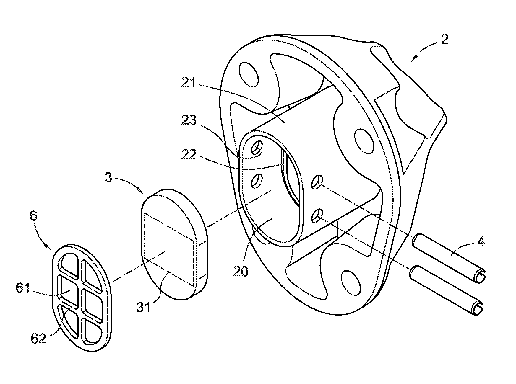
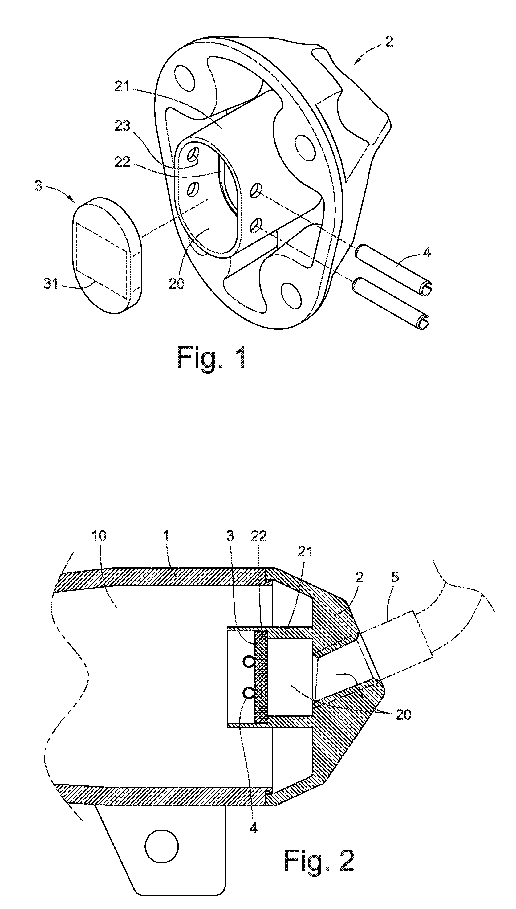
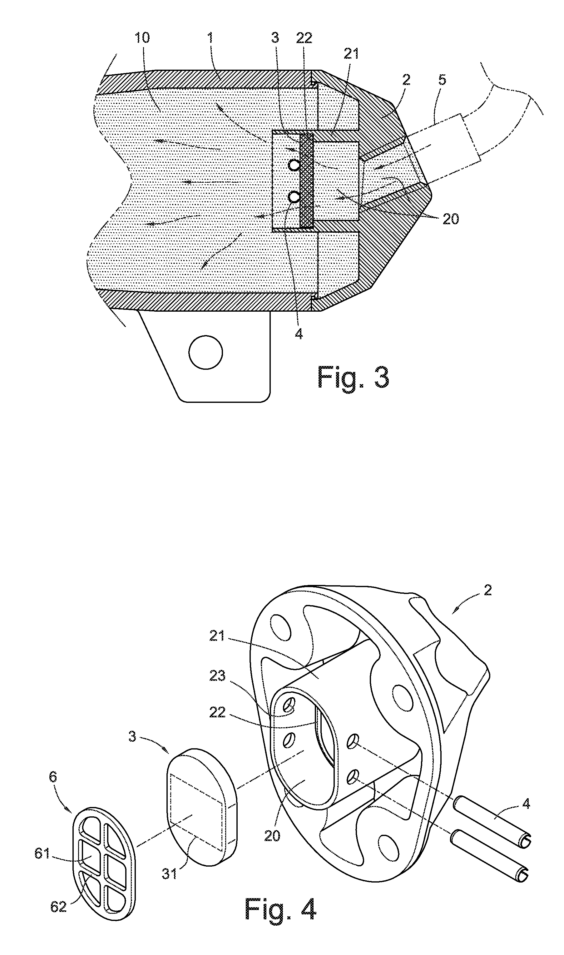
[0024]Referring to FIG. 1 and FIG. 2, a compressed air filter assembly for a nail gun according to a first embodiment of the present invention is shown. The filter assembly has an inlet aperture 20 formed at an end cap 2 of a nail gun handle 1, for guiding external compressed air therein. The inlet aperture 20 communicates with a main air chamber 10 of the nail gun handle 1. An inlet pipe 21 extends in the inlet aperture 20 and the main air chamber 10, which has a ring-shaped step 22 formed at its inner peripheral surface of its sidewall. A filter 3 is disposed in the inlet pipe 21, which is made from filter cotton or unwoven cloth.

[0025]According to the above-described structure, at least one bar 4 is provided at the sidewall of the inlet pipe 21, which transversely disposed in the inlet aperture 20 of the inlet pipe 21. In the first embodiment, two bars 4 are provided. The filter 3 is sandwiched between the at least one bar 4 and the ring-shaped step 22.

[0026]In a concrete embodim...


PUM

PropertyMeasurementUnit
softaaaaaaaaaa
service durabilityaaaaaaaaaa
stabilityaaaaaaaaaa

Abstract

An exemplary compressed air filter assembly for nail gun has an end cap at a handle of the nail gun, having an inlet aperture for guiding external compressed air therein, communicating with a main air chamber of the handle; an inlet pipe extending in the inlet aperture and the main air chamber, having a ring-shaped step formed at an inner peripheral surface of a sidewall thereof; and a filter disposed at the inlet pipe. At least one bar is provided at the sidewall of the inlet pipe, transversely disposed in the inlet aperture, and the filter being disposed between the at least one bar and the ring-shaped step. The compressed air filter assembly for nail gun utilize the at least one bar to support a center portion of the filter, which can improve the strength of the filter to resist the blasting of the compressed air.

Description

BACKGROUND[0001]The present invention relates to a compressed air filter assembly for a nail gun, and more particularly to an air filter unit installed at an end cap of a handle of a nail gun, capable of filtering dust or the like in the compressed air guided into a main air chamber of the nail gun.[0002]As generally known, a handle of a typical nail gun has a main air chamber, the compressed air being guided therein through an inlet port of an end cap disposed at a tail end of the handle. The compressed air is accommodated in a gun body of the nail gun, as a power source of driving a piston. In addition, the inlet port extends into the main air chamber to form an inlet pipe, and a filter is provided between the main air chamber and the inlet port for preventing dust or the like from entering inside. The filter is generally made from soft cotton or unwoven cloth.[0003]As shown in U.S. Pat. No. 5,259,465, U.S. Pat. No. 6,517,593, U.S. Pat. No. 6,726,080 and U.S. Pat. No. 7,122,066, a...

Claims


Application Information

Patent Timeline
Patent Type & Authority Patents(United States)
IPC IPC(8): B25C1/04B01D46/00
CPCB01D46/10B01D2265/06
Inventor HUANG, PO-FENGLAUBACH, MARCO
Owner ROBERT BOSCH TOOL
Learn More