
Modular, wall-mounted plant growing system

Active Publication Date: 2009-12-08
DEUT ABOULMAHASSINE ELIZABETH DEVON
View PDF11 Cites 47 Cited by
  • Summary
  • Abstract
  • Description
  • Claims
  • Application Information

AI Technical Summary

Benefits of technology

[0016]The modular living wall system may be applied to a vertical surface by bolting to the existing structure, a technique that more easily permits removal and replacement of individual modules. This approach also does not rely on tessellating the plane of the vertical surface, so that the modules may be arranged in any desired matrix or array. The modules may be spaced from the existing structure by simple standoffs secured to the back surface of the base panel.
[0017]Alternatively, the invention provides a plurality of davits or similar supports at the top edge of the wall, with suspending cables extending downwardly to connect to the living wall panels in vertically supporting fashion. This technique enables application of the living wall concept to an existing building wall without requiring support components that pierce the building wall, so that the building's weatherproofing remains intact. It also enables applications to walls having substantial glass surfaces and the like.

Problems solved by technology

Due to the rapid urbanization of the 20th century, there has been a substantial loss of these fertile lands.
The conversion of this land from agrarian to urban uses has led to local environmental effects that are detrimental to the local urban inhabitants and well as the global environment.
For example, vegetation that grew on these arable lands converted carbon dioxide to oxygen, and urbanization decreases this natural, beneficial process.
In addition, urban population concentrations generate large amounts of air pollution.
This method also creates an aesthetically pleasing environment, but there are some problems with this practice.
It takes decades for a structure to be enveloped by vegetation.
This method is also limited because only a small number of species of vegetation are suitable for use with this method, and there is a limit to the climbing height of most vines.
The prior art is deficient in providing plant growing systems that are easily mounted on existing building walls and similar structures.
These factors result in cost factors that render them impractical for a building owner or operator, even though the urban population as a whole would benefit from the addition of the vegetation.

Method used


Image

  • Modular, wall-mounted plant growing system
  • Modular, wall-mounted plant growing system
  • Modular, wall-mounted plant growing system

Examples


Embodiment Construction

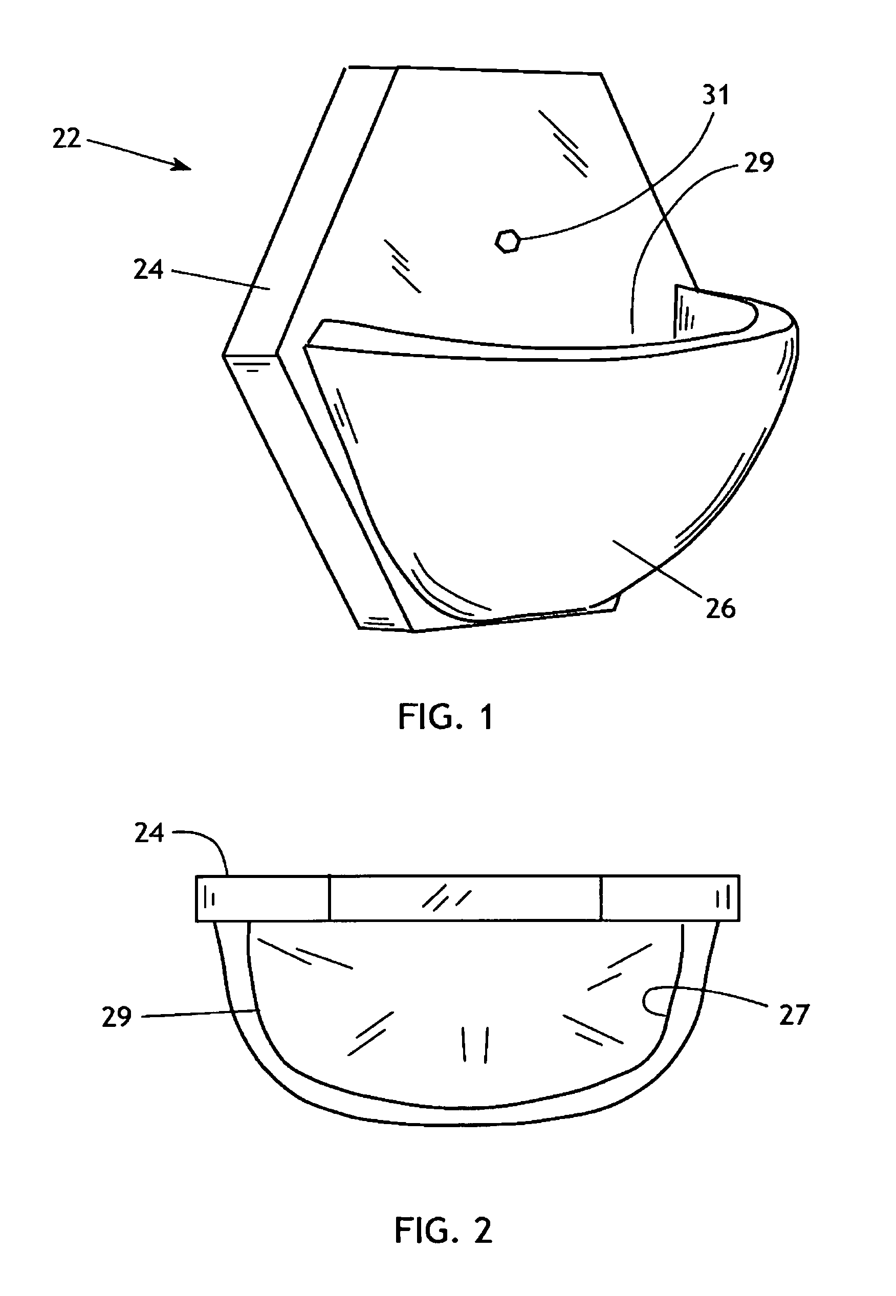
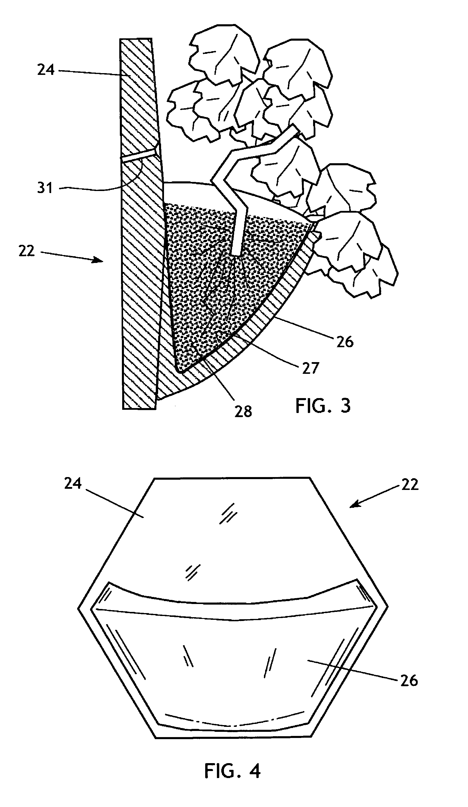
[0034]The present invention generally comprises a living wall system featuring modular components that may be applied to a wide variety of structures. With regard to FIGS. 1-5, one embodiment of the invention provides a plurality of living wall modules 21 that are constructed likes tiles, and are produced in two models: planter tiles 22 and base tiles 23. Both models include a base panel 24 having a perimeter configured as a geometric shape that permits tessellation of a plane; i.e., the base tiles and planter tiles may be installed in edge-abutting fashion as an array that covers a plane with no gaps therebetween. Although the tile formats shown herein involve base tiles and planter tiles having the same geometric forms, they may have complementary forms that enable tessellation, as is known in the prior art. In the illustrated embodiment the base panel is formed as a hexagon having horizontal upper and lower edges for both the planter tiles and base tiles.

[0035]Each planter tile 2...


PUM


Abstract

A living wall comprises a plurality of planter tiles and base tiles configured to be joined in edge abutting fashion to tessellate a vertical surface. Planter tiles include a curved coffer wall extending from a front surface of the base panel to define an upwardly opening container for soil and plants. Base tiles and planter tiles may be fabricated from a porous material that allows a soaker supply at the top of the tile layout to water the entire vertical matrix by seepage through the tiles. In another embodiment, bio-blocks in stacked array having cavities for soil and water treatment media, and cladding panels are secured to one surface of the stacked array with openings for plants growing in the soil media.

Description

CROSS-REFERENCE TO RELATED APPLICATIONS[0001]This application claims the benefit of the filing date of Provisional Application Ser. No. 60 / 619,093, filed Oct. 15, 2004.FEDERALLY SPONSORED RESEARCH[0002]Not applicable.SEQUENCE LISTING, ETC ON CD[0003]Not applicable.BACKGROUND OF THE INVENTION[0004]1. Field of the Invention[0005]This invention relates to systems for biological treatment and support on the vertical walls of manmade structures and, in particular, to plant growing systems that are modular and adaptable to many different site and building conditions.[0006]2. Description of Related Art[0007]As urban and suburban density increase, human impact on local flora and fauna as well as migrating species and their required habitat becomes ever greater. The health of all bio-regions effects all creatures—humans can no longer afford the naive perspective of separating ourselves from the health of the planet—beginning with one's own particular bio-region. Loss of habitat for local wil...

Claims


Application Information

Patent Timeline
IPC IPC(8): A01G9/02
CPCA01G9/025Y02P60/20
Inventor DEUTSCH-ABOULMAHASSINE, ELIZABETH DEVON
Owner DEUT ABOULMAHASSINE ELIZABETH DEVON
Learn More