
Optical intermediary component and optical daughter card module

a technology of intermediary components and optical daughter cards, applied in the field of optical daughter cards, can solve the problems of limiting application, increasing assembly and manufacturing costs of relative elements, and the bandwidth of conventional metal conductor connection technology, and achieves the effects of reducing cost, high alignment tolerance, and easy assembly

Active Publication Date: 2009-12-01
IND TECH RES INST
View PDF16 Cites 1 Cited by
  • Summary
  • Abstract
  • Description
  • Claims
  • Application Information

AI Technical Summary

Benefits of technology

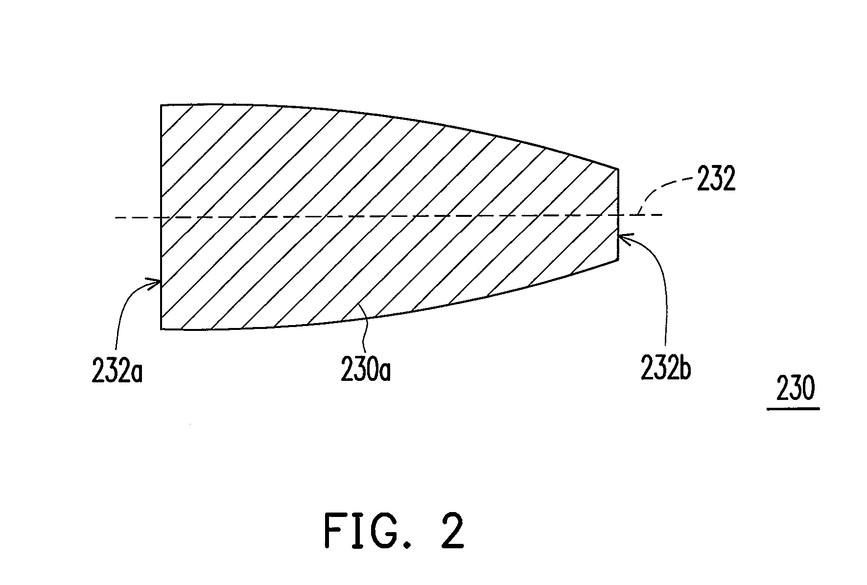
[0011]In the present invention, the area of the light incident surface is greater than that of the light emitting surface in the light guiding portion, so a high alignment tolerance is provided between the output optical path and the optical intermediary component, thus making the assembly easier and reducing the cost.

Problems solved by technology

With rapid progress in multimedia applications, the bandwidth of the conventional metal conductor connection technology is coming to a limit.
Restricted by the outer diameter, a precise assembly technology and tools are needed, but may indirectly lead to higher assembly and manufacturing costs of relative elements, thus limiting the application thereof.

Method used


Image

  • Optical intermediary component and optical daughter card module
  • Optical intermediary component and optical daughter card module
  • Optical intermediary component and optical daughter card module

Examples


Embodiment Construction

[0023]Reference will now be made in detail to the present preferred embodiments of the invention, examples of which are illustrated in the accompanying drawings. Wherever possible, the same reference numbers are used in the drawings and the description to refer to the same or like parts.

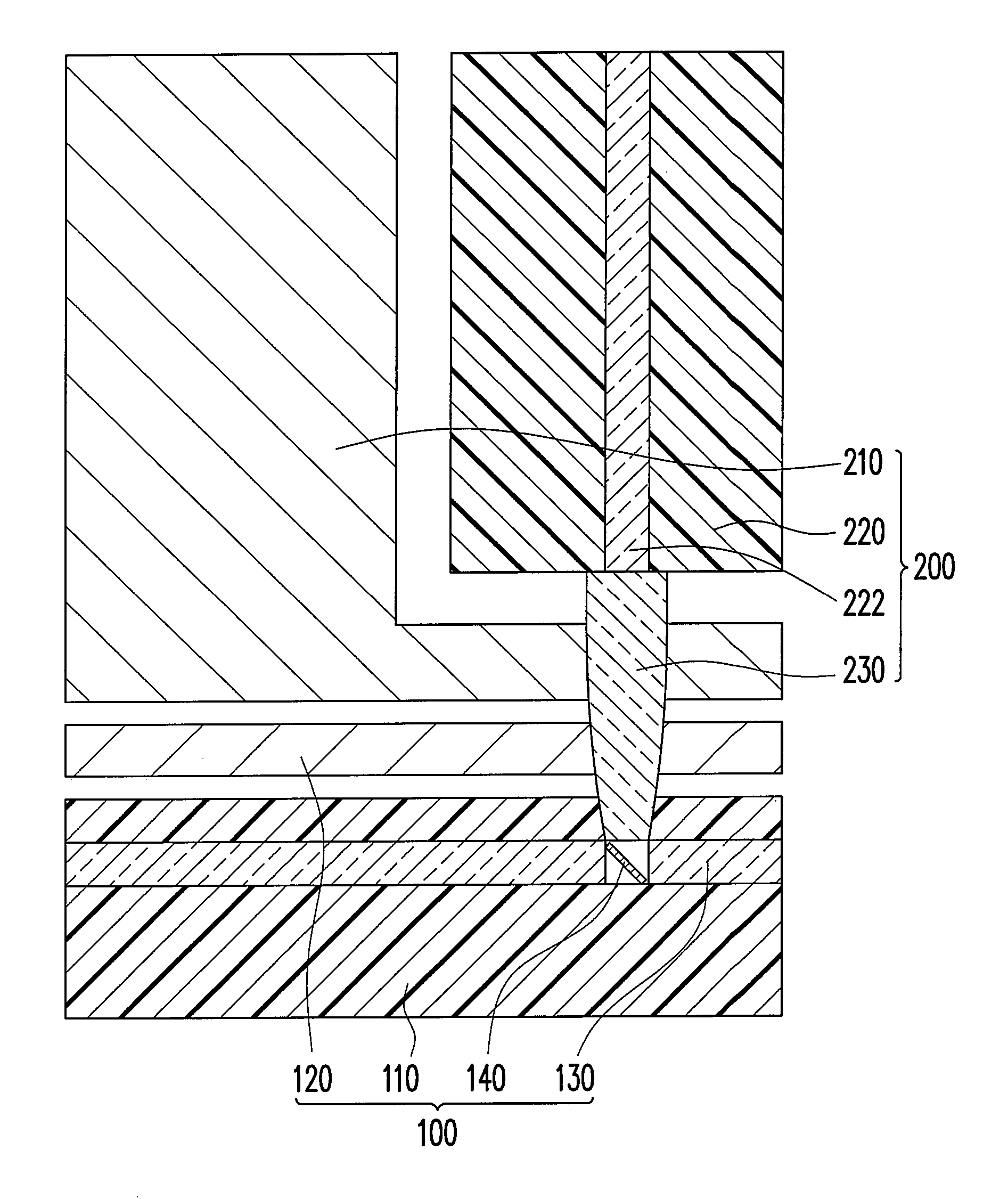
[0024]FIG. 1 is a cross-sectional view of an optical daughter card module installed on an optical parent card module according to an embodiment of the present invention. Referring to FIG. 1, in this embodiment, an optical daughter card module 200 is suitable for being detachably installed on an optical parent card module 100. The optical parent card module 100 includes a parent card 110, a parent card positioning component 120 fixed to the parent card 110, and an input optical path 130 in the parent card 110. The optical daughter card module 200 includes a daughter card positioning component 210, a daughter card 220, and an optical intermediary component 230.

[0025]In particular, the daughter card pos...


PUM


Abstract

An optical intermediary component is suitable for guiding a light from an output optical path into an input optical path. The optical intermediary component includes a light guiding portion extending along a light axis. The light guiding portion has a light incident surface and a light emitting surface at two opposite ends thereof respectively. The light from the output optical path passes through the light incident surface and the light emitting surface of the light guiding portion in sequence, and is guided into the input optical path. The area of the light incident surface is greater than that of the light emitting surface. Therefore, a high assembly tolerance may reduce the manufacturing and assembly cost.

Description

CROSS-REFERENCE TO RELATED APPLICATION[0001]This application claims the priority benefit of Taiwan application serial no. 96151030, filed on Dec. 28, 2007. The entirety of the above-mentioned patent application is hereby incorporated by reference herein and made a part of specification.BACKGROUND OF THE INVENTION[0002]1. Field of the Invention[0003]The present invention generally relates to an optical daughter card module, in particular, to an optical intermediary component applied in an optical daughter card module.[0004]2. Description of Related Art[0005]With rapid progress in multimedia applications, the bandwidth of the conventional metal conductor connection technology is coming to a limit. The broadband and anti-electromagnetic interference characteristics of the optical connection technology meet the technical requirements in the development of multimedia applications. Optical fiber is a light guiding element for transmitting telecommunication signals through the total reflec...

Claims


Application Information

Patent Timeline
Patent Type & Authority Patents(United States)
IPC IPC(8): G02B6/26G02B6/36G02B6/42
CPCG02B6/43G02B6/262G02B6/4214
Inventor LIN, SHIN-WAYJANG, BEN-HWA
Owner IND TECH RES INST
Learn More