
System and method for measuring color on a printing press

Active Publication Date: 2009-12-01
BALDWIN AMERICAS CORP
View PDF35 Cites 14 Cited by
  • Summary
  • Abstract
  • Description
  • Claims
  • Application Information

AI Technical Summary

Benefits of technology

[0006]In one embodiment of the invention, the image processing apparatus further includes a beamsplitter to separate the acquired image into multiple beams. In another embodiment of the invention, the first and second processors generate first and second signals, respectively. In another embodiment of the invention, the image processing apparatus further includes a third processor that analyzes the first and second signals to correct for the effects of scattered l

Problems solved by technology

There may be a difficulty with current image processing systems, especially with those utilizing an RGB camera, in developing color transforms to transform from the RGB filters to the density or colorimetry filters.
This may limit the number of ink colors than can be effectively monitored using the image processing system.

Method used


Image

  • System and method for measuring color on a printing press
  • System and method for measuring color on a printing press
  • System and method for measuring color on a printing press

Examples


Embodiment Construction

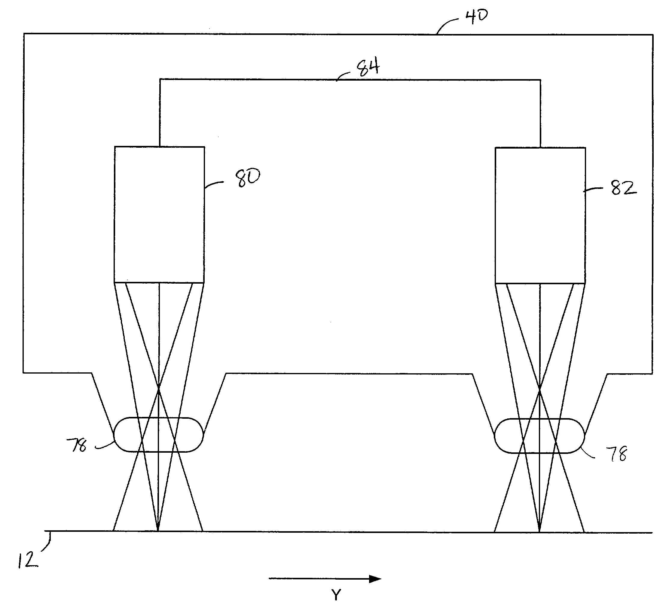
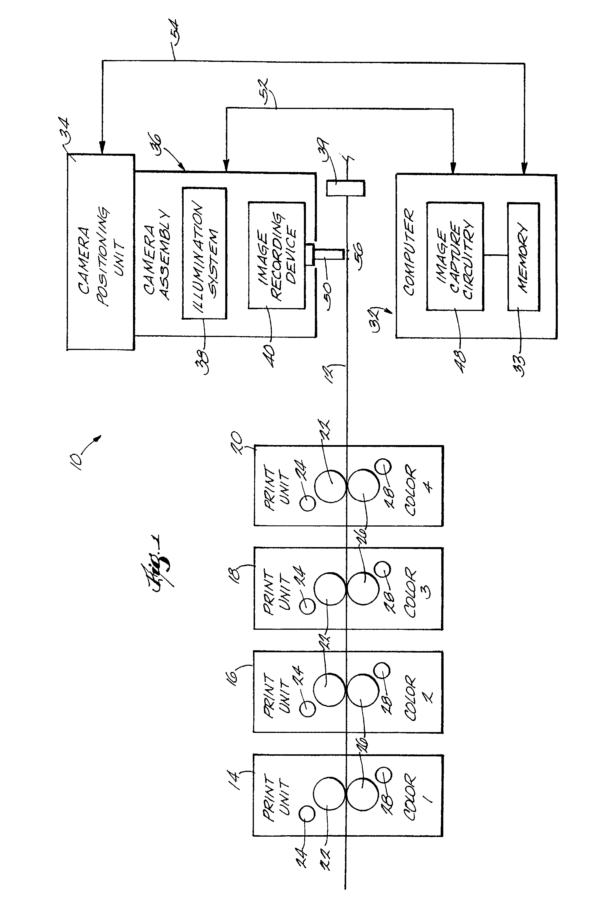
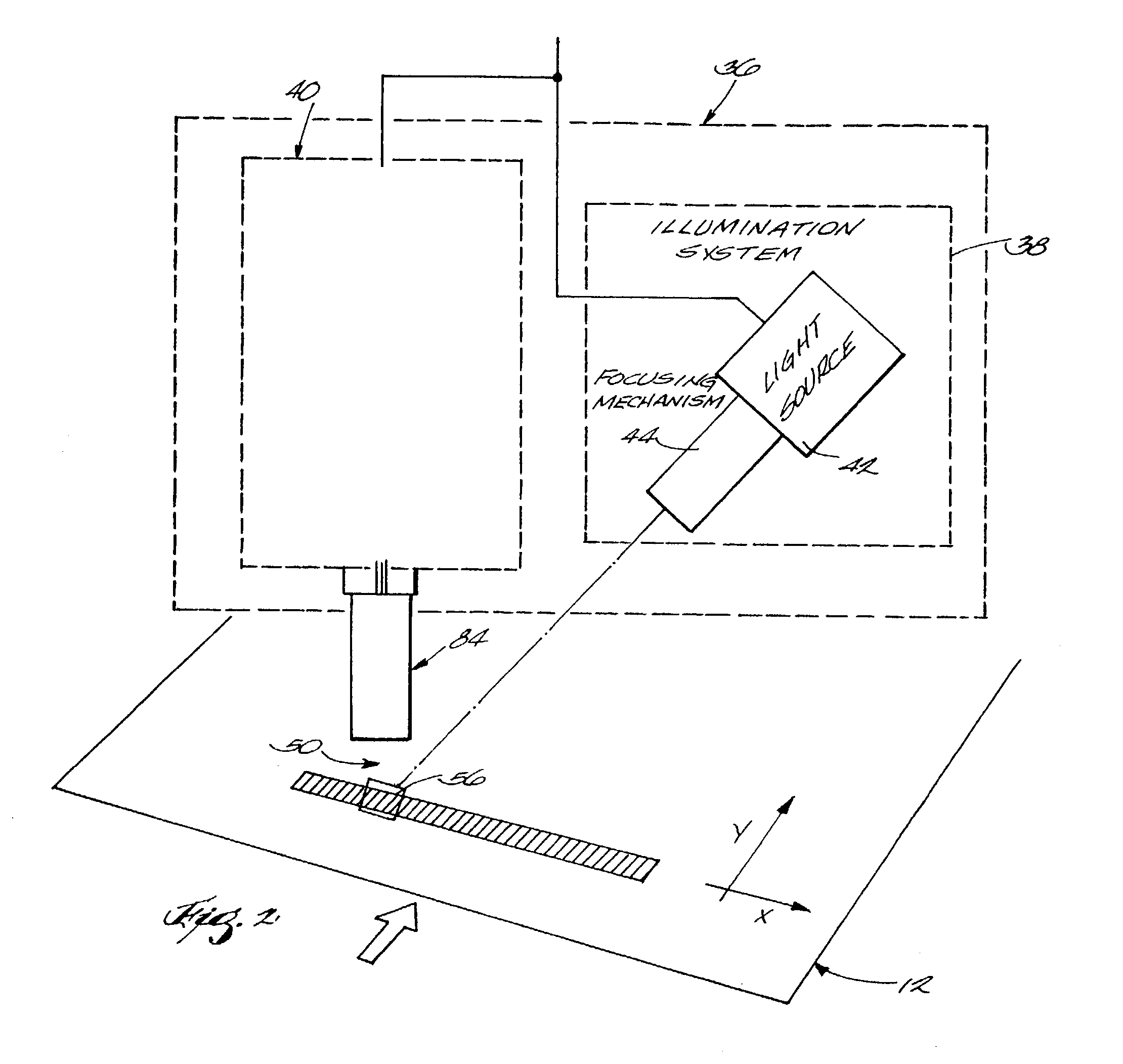
[0022]Referring to FIG. 1, a printing system 10 for printing a multi-color image upon a web 12 is illustrated. In the illustrated embodiment, four printing units 14, 16, 18, and 20 each print one color of the image upon the web 12. This type of printing is commonly referred to as web offset printing. Each print unit 14, 16, 18, 20 includes an upper blanket cylinder 22, an upper printing plate cylinder 24, a lower blanket cylinder 26, and a lower printing plate cylinder 28. In the printing system 10, colors 1, 2, 3, and 4 on units 14, 16, 18, and 20 respectively, are black (K), cyan (C), magenta (M), and yellow (Y). However, it is understood that any colors of ink may be effectively analyzed by the present invention. The location of the printing units 14, 16, 18, and 20 relative to each other is determined by the printer, and may vary.

[0023]In the illustrated embodiment, the printing press is a web offset press. It is contemplated, however, that the present invention be applicable to...


PUM


Abstract

An image processing apparatus and method for measuring spatial and spectral information from an image of a printed substrate. The image processing apparatus processes the spatial and spectral information from the same acquired image using first and second processors. In some embodiments, the image processing apparatus processes the spatial information from a first acquired image and the spectral information from a second acquired image, the first and second acquired images being of the same point on the printed substrate, acquired at separate times during the travel of the printed substrate. In other embodiments, the image processing apparatus processes the spatial and spectral information from the same acquired image using the same processor.

Description

FIELD OF THE INVENTION[0001]The present invention relates to an apparatus and method for measuring spectral and spatial information on a printing press.BACKGROUND OF THE INVENTION[0002]In the printing industry, a desired image is repeatedly printed on a continuous web or substrate such as paper. In a typical printing process, the continuous web is slit in the longitudinal direction (the direction of web movement) to produce a plurality of continuous ribbons. The ribbons are aligned one on top of the other, folded longitudinally, and then cut laterally to produce a plurality of multi-page, approximately page-length segments, each of which is termed a “signature”. The term signature also encompasses a single printed sheet that has or has not been folded.[0003]To monitor the print quality on a signature, various methods may be used to measure the color quality of the printed signature. One method includes printing a color bar having multiple color patches of different known colors and ...

Claims


Application Information

Patent Timeline
IPC IPC(8): G06K9/00B41F33/00G01J3/28G01J3/50
CPCB41F33/0036G01J3/2823G01J3/524G01J3/502G01J3/50G01J3/513
Inventor NOFFKE, PATRICK JAMESYOUNK, PATRICKMOERSFELDER, BRADLY S.
Owner BALDWIN AMERICAS CORP
Learn More