
System and method for detecting onset of structural failure

a structural failure and detection system technology, applied in the direction of mechanical measuring arrangements, instruments, force/torque/work measurement apparatus, etc., can solve the problems of posing both financial risk and a threat to personal and public safety, and unable to detect the onset of structural failure before it occurs

Active Publication Date: 2009-11-24
AEROJET ROCKETDYNE OF DE
View PDF12 Cites 16 Cited by
  • Summary
  • Abstract
  • Description
  • Claims
  • Application Information

AI Technical Summary

Problems solved by technology

Structural failure can be unpredictable and catastrophic, posing both financial risk and a threat to personal and public safety.
Traditional destructive testing techniques are effective at determining a failure threshold, but cannot generally detect the onset of failure before it occurs.
This presents a significant problem for non-destructive testing, in which unanticipated structural failure can result in both economic loss and safety hazards.
Post-testing failures (i.e., during construction or use) may be even more serious, but are even more difficult to predict.
Traditional structural inspection techniques suffer from limited accessibility and require significant time and expertise.
This forces an economic tradeoff between the inspection cycle and its cost, resulting in inspections that are at best periodic, or that occur only after a significant event such as earthquake, fire, or accident.
Moreover, traditional inspection techniques tend to rely on visual surveys which are quite different from the methods employed during structural testing.
This makes correlation between the two approaches difficult, further compromising the ability of traditional structural testing and inspection to detect the onset of structural failure before it actually occurs.
Nonetheless prior art SHM utility remains limited because the systems do not apply the same monitoring techniques as those used during structural testing, and because the prior art cannot detect the onset of failure before it has occurred, at least on a local scale.

Method used


Image

  • System and method for detecting onset of structural failure
  • System and method for detecting onset of structural failure
  • System and method for detecting onset of structural failure

Examples


Embodiment Construction

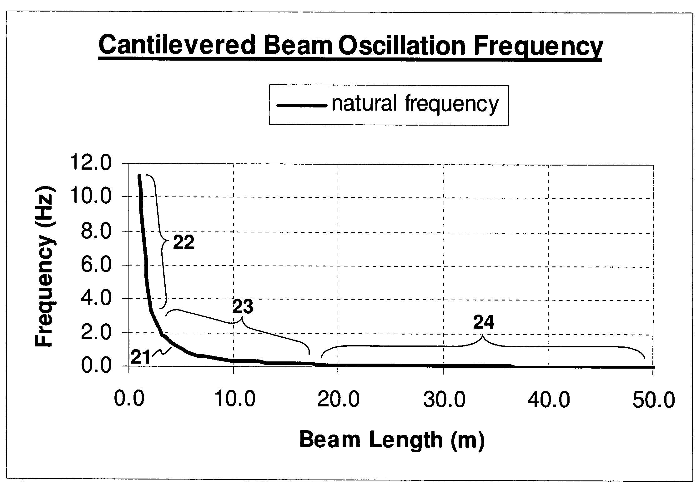
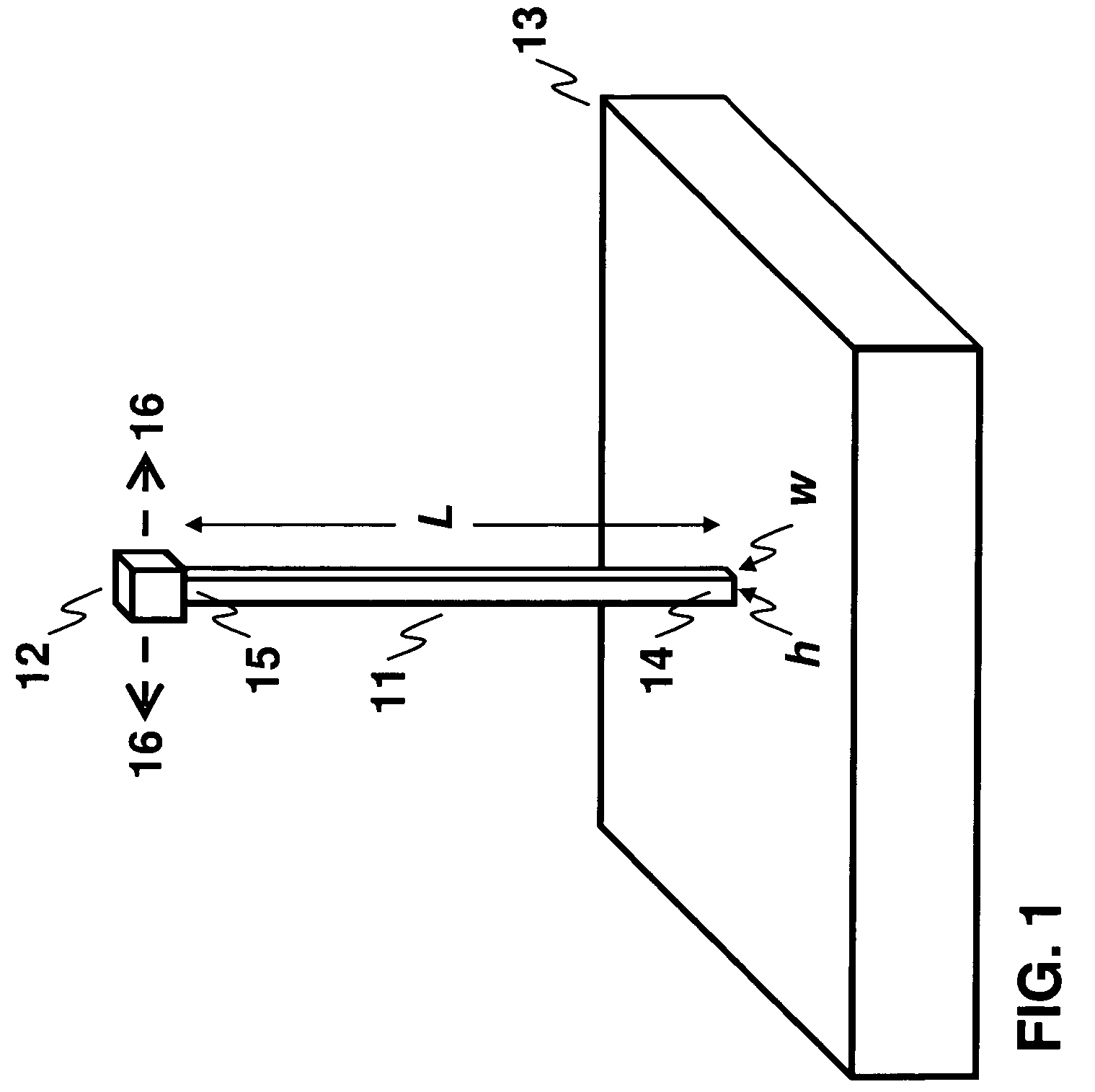
[0023]FIG. 1 is a perspective view of vertical cantilevered beam 11 subject to compressive load 12. FIG. 1 shows cantilevered beam 11 of length L with transverse dimensions h and w, loading mass 12 with mass m, and immobile base 13. Beam 11 is vertically oriented, with lower end of beam 14 affixed to base 13 and upper end of beam 15 affixed to loading mass 12. Beam 11 has small mass as compared to mass m of loading mass 12, and loading mass 12 has small dimensions as compared to length L of beam 11.

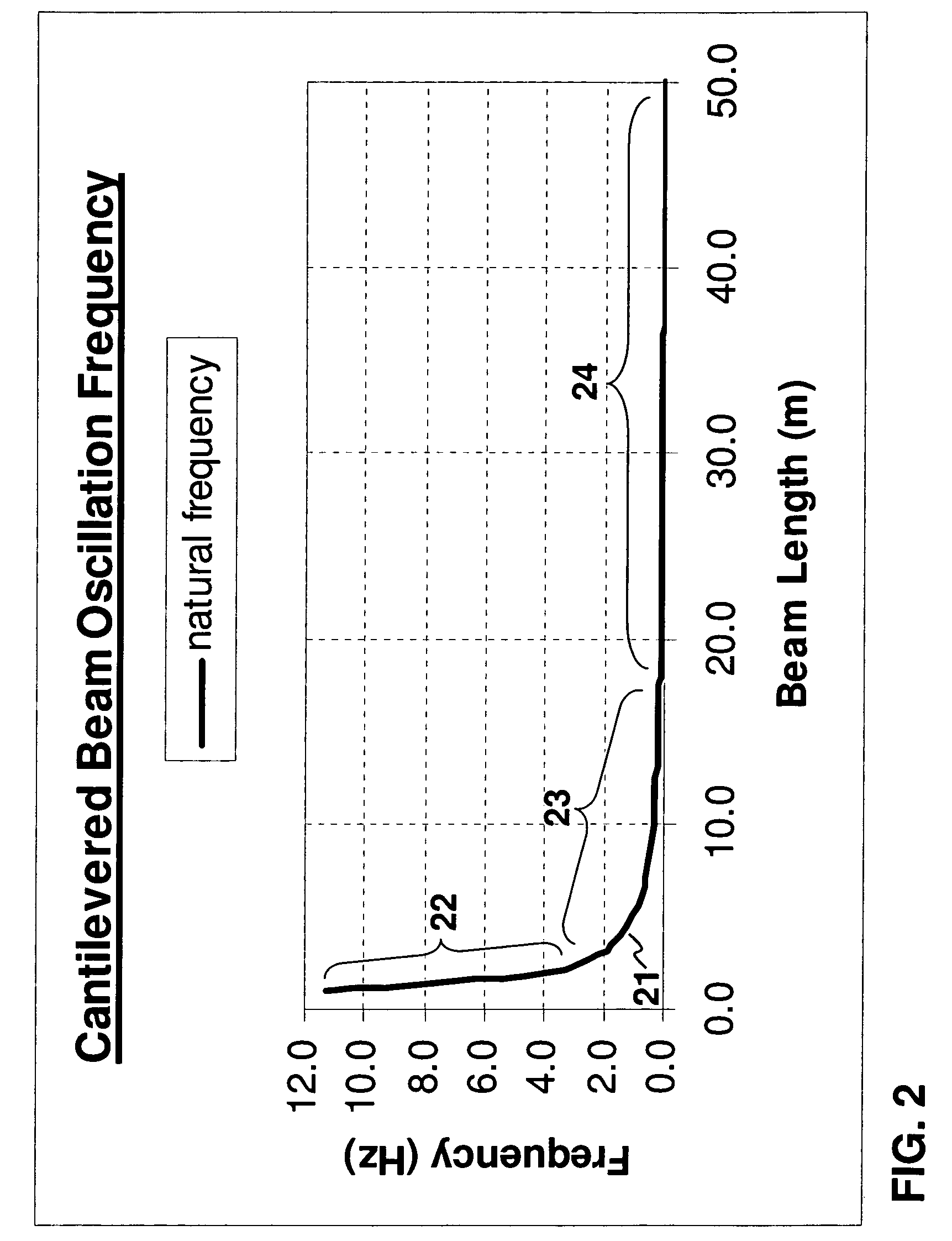
[0024]In this arrangement, loading mass 12 and upper end 15 of beam 11 are susceptible to small-amplitude oscillations generally contained in a horizontal plane parallel to base 13. Arrows 16 indicate one possible sense of this oscillation, which is spring-like with natural frequency f determined by effective spring constant k and mass m:

[0025]f=12⁢⁢π⁢km.(1)

[0026]The effective spring constant k characterizes the stiffness of the beam. For a vertically cantilevered beam the spring constant...


PUM


Abstract

A system for detecting the onset of structural failure in a structural element subject to a mechanical load comprises a metering array, a signal processor, and an output processor. The metering array measures physical quantities associated with the structural element. The signal processor transforms the measured physical quantities into a series of sample mode spectra, and the output processor generates output as a function of the series of sample mode spectra. Methods are also disclosed for detecting the onset of failure in a structural element subject to a mechanical load, for structural testing, and for structural health monitoring.

Description

BACKGROUND OF THE INVENTION[0001]The present invention relates generally to structural testing and structural monitoring, and in particular to detecting the onset of structural failure by analysis of sample oscillation mode spectra.[0002]Structural failure can be unpredictable and catastrophic, posing both financial risk and a threat to personal and public safety. Traditional destructive testing techniques are effective at determining a failure threshold, but cannot generally detect the onset of failure before it occurs. As a result, safety margins must be determined a priori or by trial and error.[0003]This presents a significant problem for non-destructive testing, in which unanticipated structural failure can result in both economic loss and safety hazards. Post-testing failures (i.e., during construction or use) may be even more serious, but are even more difficult to predict.[0004]Traditional structural inspection techniques suffer from limited accessibility and require signifi...

Claims


Application Information

Patent Timeline
Patent Type & Authority Patents(United States)
IPC IPC(8): G06F3/00
CPCG01M5/0025G01N3/32G01N3/34G01N29/12G01N29/46G01M5/0033G01N2291/048G01N2203/0007G01N2203/001G01N2203/0039G01N2203/0055G01N2203/0062G01N2203/0067G01N2203/0073G01N2203/0075G01N2203/0244G01N2203/0658G01N2291/0258G01N2291/0427
Inventor CIPRA, DALE O.
Owner AEROJET ROCKETDYNE OF DE
Learn More