
Spray apparatus and method for the repair of can ends

a technology of spraying apparatus and can end, which is applied in the direction of spraying apparatus, movable spraying apparatus, liquid spraying apparatus, etc., can solve the problems of generating overspray, affecting the quality of protective coatings, and affecting the appearance of products that are not attractive to consumers, so as to avoid overspray, reduce the volume of overspray, and increase the film weight

Active Publication Date: 2009-11-24
STOLLE MACHINERY CO LLC
View PDF12 Cites 8 Cited by
  • Summary
  • Abstract
  • Description
  • Claims
  • Application Information

AI Technical Summary

Benefits of technology

The solution significantly reduces downtime for cleaning and maintenance by minimizing overspray and allows for precise application of protective coatings, enhancing machine efficiency and product quality by ensuring consistent film weight application even in humid conditions.

Problems solved by technology

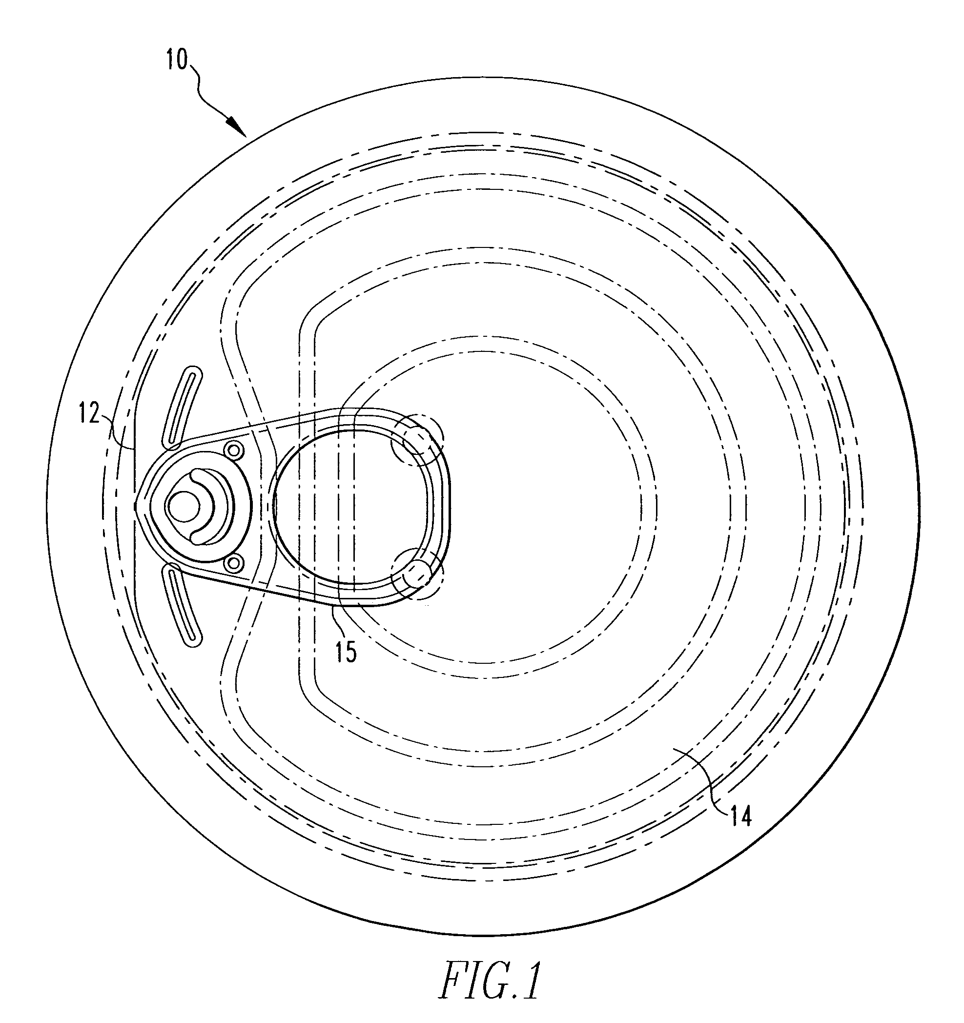
During the conversion process, damage to the protective coating typically occurs while forming the score that defines the tear panel or opening panel of the can end.
Any oxidation, corrosion or rust on the surface of the can end represents an unattractive product appearance to the consumer and is unacceptable to canmakers in general.
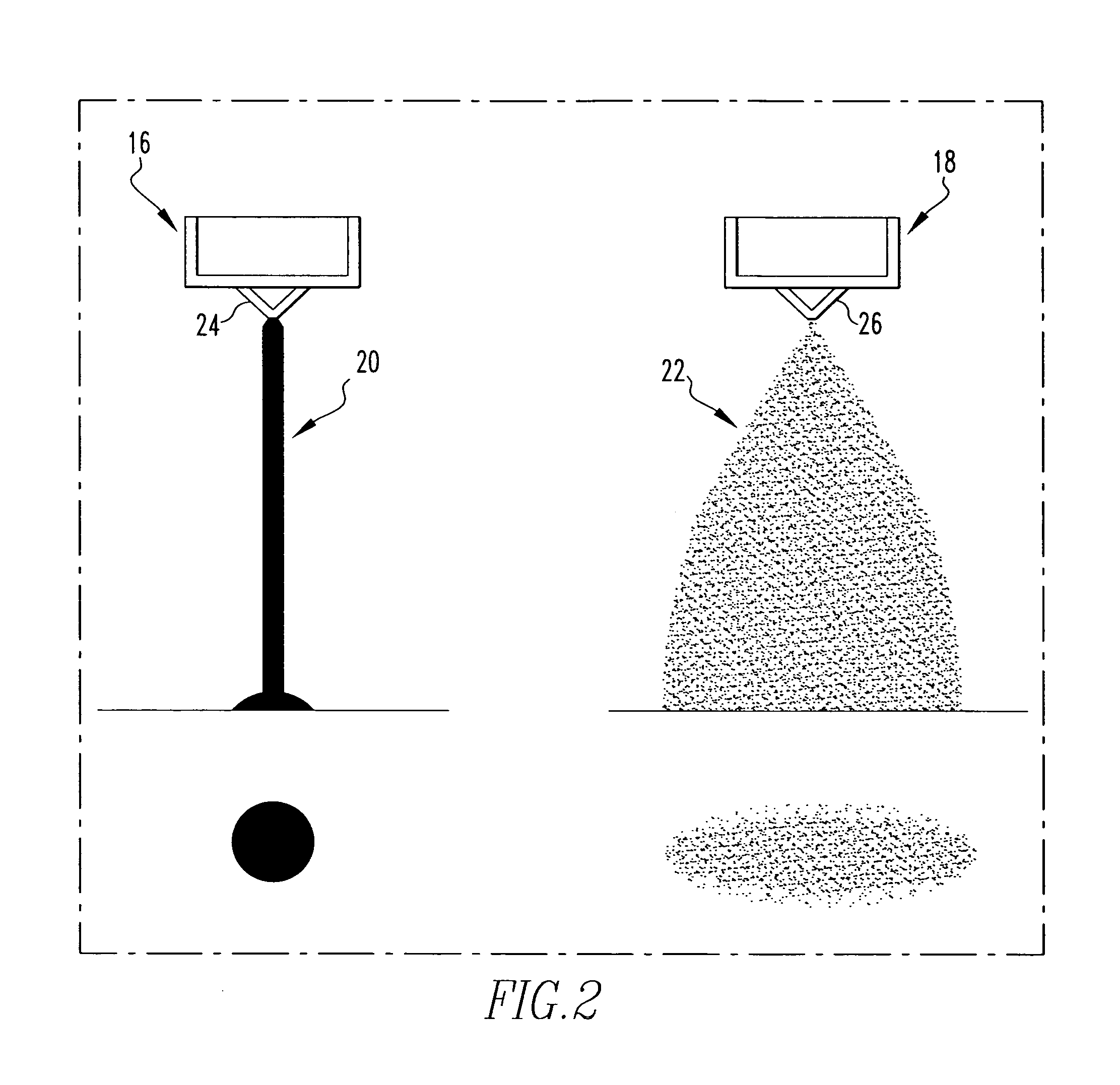
The problem with the atomization method is that it generates overspray which is detrimental to the efficiencies of the machine due to the extensive cleaning required on the surrounding transfer mechanism or belt of the machine.
The two part epoxy coating mixtures commonly used as a fluid is difficult to manage on a continuously operating machine when overspray occurs because the fluid, repair fluid, lacquer or paint builds up on the surrounding transfer mechanism of the machine, and requires routine cleaning and maintenance to keep the machine running efficiently.
The solid stream nozzle provides prolonged stream integrity, which results in delayed breakup and drop formation after leaving the nozzle orifice.
Even at this reduced film weight, the industry accepted atomization spray head presents overspray problems.
Also, the prior art atomized spray head does not apply enough film weight to the can ends in certain environments and contaminates the transfer mechanism, belt or machine because of overspray.

Method used


Image

  • Spray apparatus and method for the repair of can ends
  • Spray apparatus and method for the repair of can ends
  • Spray apparatus and method for the repair of can ends

Examples


Embodiment Construction

[0025]For purposes of the description hereinafter, the terms “upper”, “lower”, “vertical”, “horizontal”, “top”, “bottom”, “aft”, “behind”, “forward”, “rear”, “beneath”, “below” and derivatives thereof shall relate to the invention, as it is oriented in the drawing FIGS. However, it is to be understood that the invention may assume various alternative configurations except where expressly specified to the contrary. It is also to be understood that the specific elements illustrated in the drawings and described in the following specification are simply exemplary embodiments of the invention. Therefore, specific dimensions, orientations and other physical characteristics related to the embodiments disclosed herein are not to be considered limiting.

[0026]As employed herein, the term “number” refers to one or more than one (i.e., a plurality). As employed herein, the term “fastener” refers to any suitable fastening, connecting or tightening mechanism expressly including, but not limited ...


PUM


Abstract

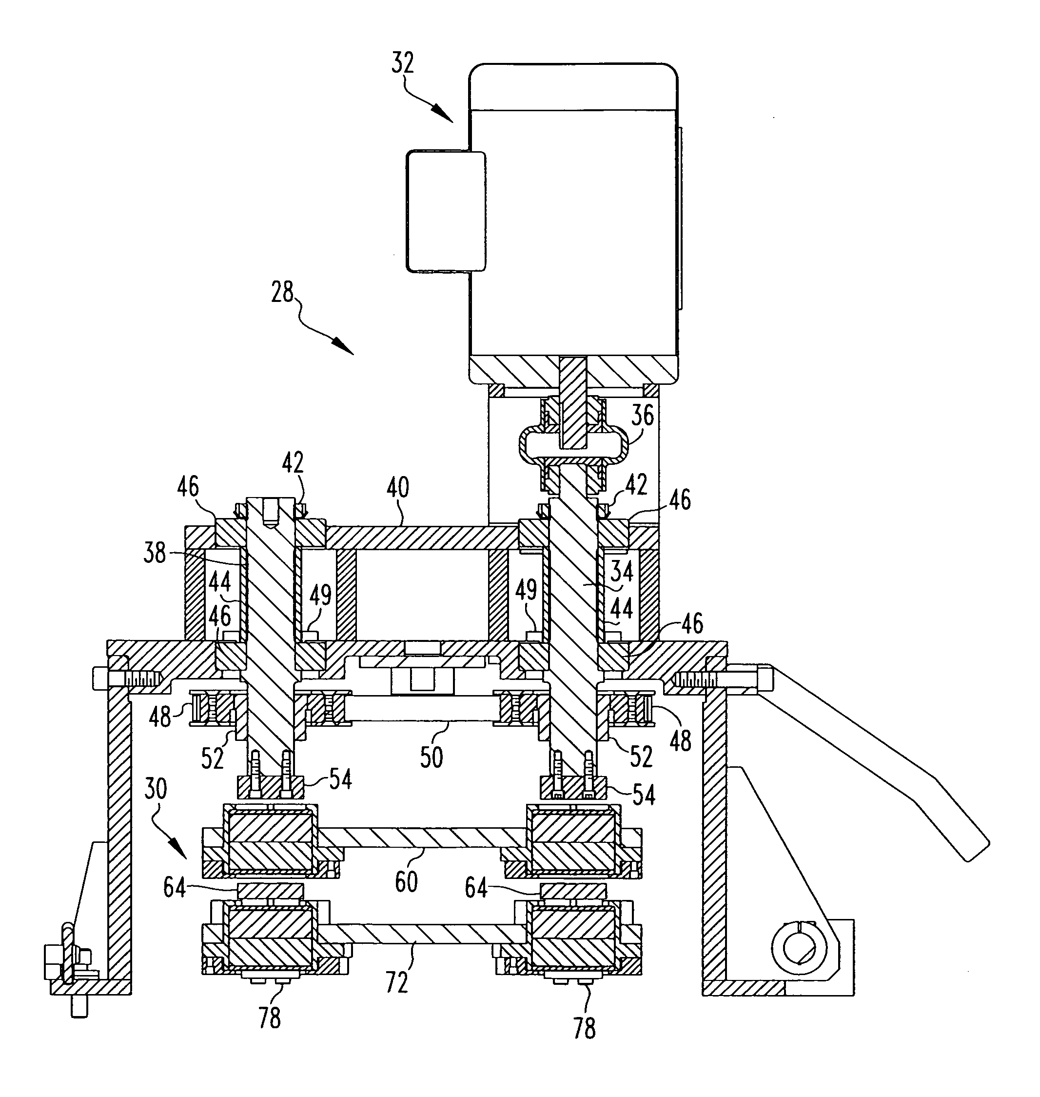
This invention generally relates to a spray apparatus and a method useful in the repair of coating adhered to can ends used in the food and beverage packaging industries. The spray apparatus has one or more elongated shafts rotatably coupled to a frame. One or more bearing members are rotatably coupled to the shafts. One or more plates are rotatably coupled to the bearing members. One or more spray guns are coupled to the plates. The spray guns of the spray apparatus are structured to apply fluid to the can end with a solid stream emitted from the spray guns in a circular pattern. A method for the repair of coating adhered on a can end is provided as well.

Description

FIELD OF THE INVENTION[0001]This invention generally relates to a spray apparatus and a method useful in the manufacture of can ends used in the food and beverage packaging industries. More specifically, the invention provides a spray apparatus and a method for use in the corrosion preventative repair of tooling induced damage to can end coatings, which may occur to coated steel can ends during the conversion of a steel shell into a full open or easy open food or beverage can end.BACKGROUND OF THE INVENTION[0002]Many can bodies for food, beverages or other products are provided with easy open can ends that are characterized by having a pull tab attached to the can end which is used to fracture a tear panel on the can end defined by a score line on the can end. The pull tab may be lifted to depress the tear panel in order to provide an opening in the can end for dispensing the contents of the container.[0003]Likewise, many food products are sold in can bodies provided with full open ...

Claims


Application Information

Patent Timeline
Patent Type & Authority Patents(United States)
IPC IPC(8): B05B3/00B05B13/06B05C19/00
CPCB05C5/0216
Inventor MCELDOWNEY, CRAIG ALLANSTAMMEN, DENNIS CORNELIUS
Owner STOLLE MACHINERY CO LLC
Learn More