
Ultra-low temperature bio-sample storage system

a biosample and ultra-low temperature technology, applied in the field of ultra-low temperature biosample storage system, can solve the problems of inability to meet the needs of high-efficiency thermal insulation, short survival time of conventional ult system without redundant evaporator and/or highly efficient thermal insulation, and limited temperature range and reliability of many refrigeration systems of known art, so as to achieve the effect of reducing thermal and cross-contamination transfer

Active Publication Date: 2009-11-24
REFLECT SCI
View PDF35 Cites 22 Cited by
  • Summary
  • Abstract
  • Description
  • Claims
  • Application Information

AI Technical Summary

Benefits of technology

[0008]It is a primary object of the present invention to provide a single programmable cooling and cryogenic freezing system optimized for long term storage of biological items with accurate process cooling and reliable temperature performance for critical requirements.

Problems solved by technology

Many refrigeration systems of known art have limitations in temperature range and reliability that would preclude their utilization in this demanding field of endeavor.
Depending on their configuration, the open-door time required for loading or unloading samples could allow an unacceptable rise in temperature.
Conventional ULT systems without redundant evaporators and / or highly efficient thermal insulation have a very short survival time, typically only a few hours, before loss of set point temperature, in the event of failure due to leakage of refrigerant, line blockage. motor or pump failure, electrical power outage or many other potential causes.
In known competitive refrigeration equipment, thermal insulation efficiency is often compromised in a tradeoff for cost savings.
Not only would the resultant higher operating cost be detrimental in the field of bio-sample storage, but, more importantly, high thermal insulation efficiency is an essential key factor in the survival of stored samples in the event of down time of the cooling unit, e.g. due to electrical power outages.
In many known refrigeration systems the cooling unit with electrical / electronic components is located close to floor level, where it is vulnerable to early failure under flooding conditions.

Method used


Image

  • Ultra-low temperature bio-sample storage system
  • Ultra-low temperature bio-sample storage system
  • Ultra-low temperature bio-sample storage system

Examples


Embodiment Construction

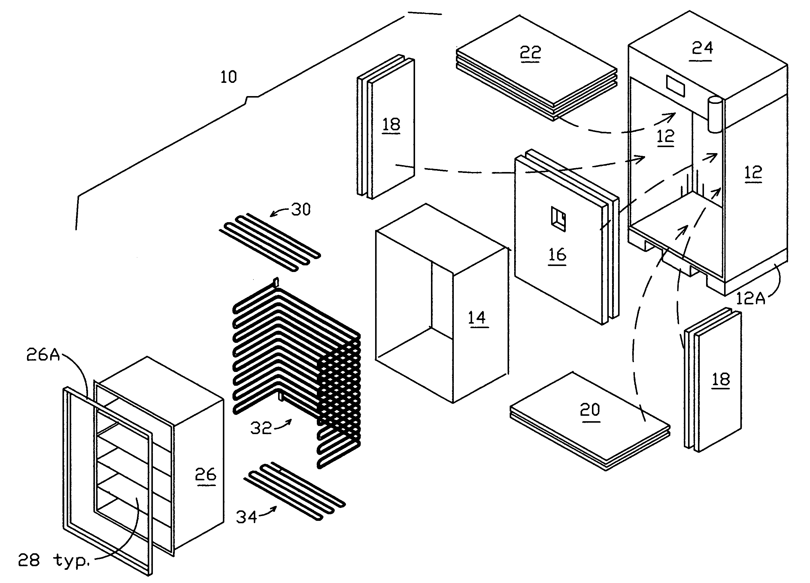
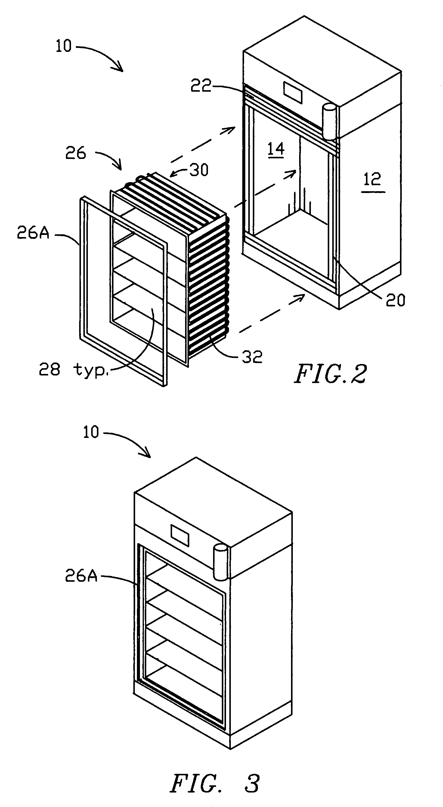
[0031]In FIG. 1, an isometric exploded view of the major component parts of a ULT freezer 10 of the present invention in an embodiment for cryogenic preservation, the outer shell 12 and inner shell 14 are five-sided boxes made from stainless steel sheet material. A set of flat insulation fillers 16-22 made from high efficiency thermal insulating material are dimensioned to line the inside of enclosure 12 at the bottom, rear, both sides and top respectively. Typically the rear filler 16 and side fillers 18 are each formed in two layers, each two inches thick. The top filler 22 may be made thicker than the others, e.g. three or four layers, while the bottom filler 16 may be made thinner, e.g. a single layer, or even omitted as an option.

[0032]The top region of freezer 10 above outer shell 12 is configured with a plenum region 24 for containing operational components such as valves and controls and is preferably provided with a display panel 24A in the front location shown, providing a...


PUM


Abstract

An ultra low temperature freezer is optimized with a combination of vacuum and fiberglass insulation for long-term biological storage with accurate process cooling with critical temperature performance. A programmable cooling and cryogenic freezing system uses sealed liquid nitrogen for cooling and freezing. A hybrid completely non-mechanical system exhibits temperature uniformity and reliability, saves space, requires extremely low operating energy and minimizes need for air conditioning in the operating environment. Top-located components control the flow of liquid nitrogen even under flooding conditions. Sectioned inner doors mitigate thermal transfer to other samples and maintain ULT while accessing the freezer.

Description

FIELD OF THE INVENTION[0001]The present invention is in the field of coolers and refrigerators; more particularly high reliability refrigerated storage systems suitable for long term storage of biological samples at ULT (ultra low temperature), typically lower than −90 degrees C.).BACKGROUND OF THE INVENTION[0002]There is an increasing need for reliable bio-sample storage at temperatures ranging from room temperature (20 degrees C.) down to ULT as low as −150° degrees C. Since these bio-samples include sensitive tissues and vaccines for protecting against pan-epidemics that could break out naturally or by acts of terrorism, the insulation systems for their storage are required to not only develop the required low temperature, but to continuously maintain that temperature accurately and reliably since even temporary loss of cooling could weaken, damage or even destroy existing supplies of vaccines, etc. Many of such stored substances are precious, e.g. very costly and having been acc...

Claims


Application Information

Patent Timeline
IPC IPC(8): F25D11/00
CPCF25D23/063F25D23/025F25D3/102F25B2500/06
Inventor DAIN, JOHN F.DAIN, ELIZABETH L.HENNEMAN, NICHOLAS J.
Owner REFLECT SCI
Learn More