
Method for controlling twisting of pool cleaner power cable

a technology for power cables and pool cleaners, applied in the direction of suction cleaners, gymnasiums, constructions, etc., can solve the problems of not always providing options, prone to twisting and coils, and inability to achieve the effect of reducing or eliminating twisting or coils

Active Publication Date: 2009-11-24
ZODIAC POOL SYST LLC
View PDF13 Cites 24 Cited by
  • Summary
  • Abstract
  • Description
  • Claims
  • Application Information

AI Technical Summary

Benefits of technology

The present invention is a pool cleaner that can move on the bottom and side walls of a swimming pool. It uses an electronic compass and a tilt sensor to determine its directional headings and uses a scanning algorithm to move in a specific pattern. The pool cleaner also has a memory device that stores the scanning algorithm and a microprocessor that compares the directional headings with the reference directional headings and adjusts its directional controller accordingly. This allows the pool cleaner to move in a smooth and efficient manner and prevents twists and loops in the power supply cable. The technical effects of the invention include improved navigation, reduced power supply cable twisting, and improved efficiency of the pool cleaner's movement.

Problems solved by technology

During operation of the pool cleaner, the repetitive turning movement of the cleaner as it moves from one sidewall of the pool to another has a tendency to form twists and coils in the floating power cable.
However, this option is not always provided even in preprogrammed pool cleaners, and is simply not possible in pool cleaners that are designed to move in a random path.
Once the directional heading of the pool cleaner deviates from the preprogrammed pattern, subsequent movement of the pool cleaner is not properly controlled so that the twisting and coiling in the power cable become excessive.
Furthermore, if the twisting continues, the intended movement of the cleaner along a preprogrammed path is interrupted, with the result that the cleaner cannot complete its cleaning cycle.
In some cases, the cleaner is displaced from the bottom or sidewall of the pool and becomes disabled or damaged by not being properly oriented.
For example, if the pool cleaner is caused to float upside down to the surface of the pool, its intake system may no longer be able to draw in the water that is necessary to cool the one or more motors that power the pumps and / or the mechanical drive mechanism, thereby resulting in damage to the motor and necessitating expensive repairs.

Method used


Image

  • Method for controlling twisting of pool cleaner power cable
  • Method for controlling twisting of pool cleaner power cable
  • Method for controlling twisting of pool cleaner power cable

Examples


Embodiment Construction

[0041]As used in this description of the invention, the term “scanning” means the pre-programmed movement of the pool cleaner during its cleaning cycle and “scanning algorithm” means the program(s) entered in the processor for controlling the pool cleaner's movement during one or more cleaning cycles.

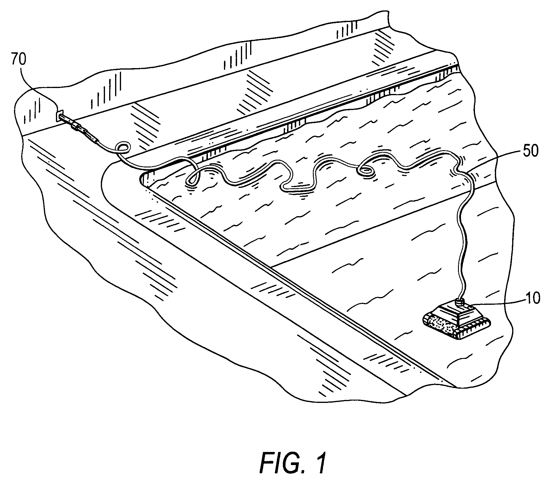
[0042]Referring to FIG. 1, a pool cleaner 10 is electrically connected via a power cable 50 to a remote poolside power supply 70. The power supply 70 can be a fixed or portable power supply located in the proximity of the pool. The power cable 50 attached to the submerged pool cleaner 10 is easy to be twisted during a cleaning operation, as shown in FIG. 1.

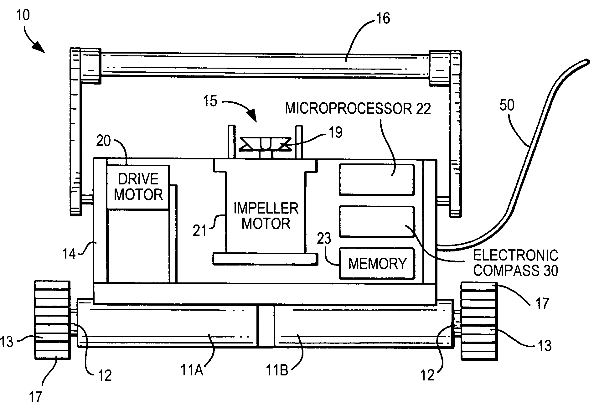
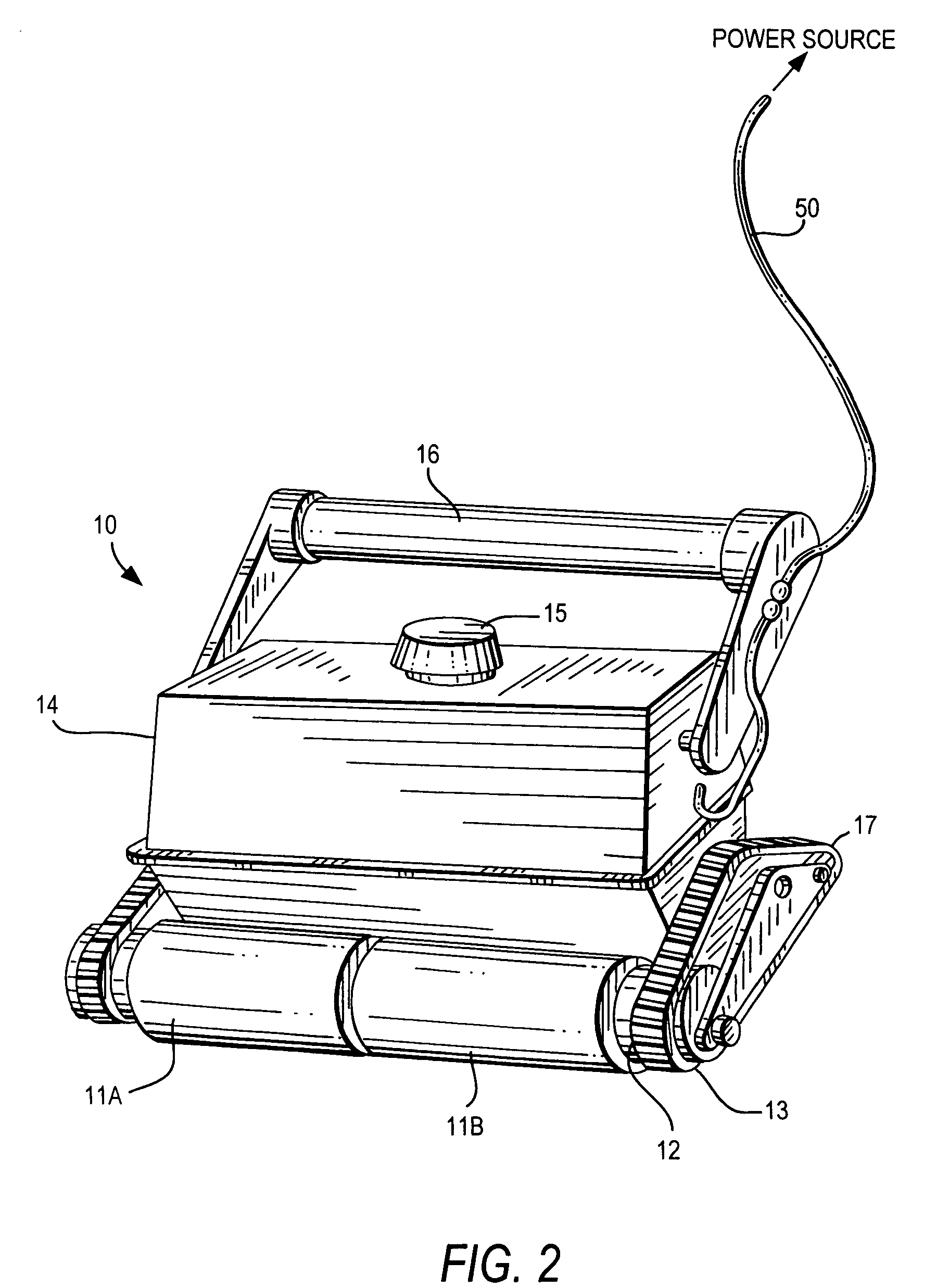
[0043]Referring to FIG. 2, the pool cleaner 10 comprises a housing 14 on which are mounted independently rotatable traction means 11A and 11B. The traction means 11A, 11B are roller brushes fabricated from a molded elastomeric polymer such as polyvinyl acetate, or PVA, that provides good traction for the pool cleaner 10 against cerami...


PUM


Abstract

An apparatus and method is provided for removing undesired twists and loops in a power supply cable attached to a robotic swimming pool cleaner during the cleaner's pre-programmed movement over the bottom and / or side walls of the pool. An on-board electronic compass determines an initial reference directional heading of the pool cleaner and the subsequent true or actual directional heading of the pool cleaner is determined intermittently or continuously as the pool cleaner moves through the program cycle. The subsequent directional headings of the moving pool cleaner are compared to the reference directional heading to provide a cumulative positive or negative value. When the cumulative value indicates that one or more complete 360° turns have been made from the reference directional heading, a correction signal is generated for immediate or delayed transmission to the directional control means to turn the pool cleaner in a direction to remove any twists or loops that have formed in the power cable.

Description

FIELD OF THE INVENTION[0001]The present invention relates to a method and a pool cleaner for removing and preventing undesired twists and coils of the pool cleaner's power cable.BACKGROUND OF THE INVENTION[0002]Self-propelled automated, or robotic pool cleaners are designed to traverse either a pre-programmed pattern or a random path across the bottom of a swimming pool for the purpose of cleaning the bottom, and in some cases, also the sidewalls of the pool. The submerged cleaner receives its power through a buoyant power supply cable, or power cable, attached to a fixed or portable poolside power supply located in the proximity of the pool.[0003]During operation of the pool cleaner, the repetitive turning movement of the cleaner as it moves from one sidewall of the pool to another has a tendency to form twists and coils in the floating power cable. If the size and configuration of the pool is known, it is possible to pre-program the operation of the pool cleaner to periodically re...

Claims


Application Information

Patent Timeline
Patent Type & Authority Patents(United States)
IPC IPC(8): E04H4/16
CPCE04H4/1654
Inventor KATZ, PESACH
Owner ZODIAC POOL SYST LLC
Learn More