
Performing model-based root cause analysis using inter-domain mappings

a model-based root cause and mapping technology, applied in the field of network modeling, can solve the problems of extra computer resources, such as processing speed or memory, imposing an extra ordinary long time to obtain, and overburdening the computer system

Active Publication Date: 2009-11-17
VMWARE INC
View PDF1 Cites 5 Cited by
  • Summary
  • Abstract
  • Description
  • Claims
  • Application Information

AI Technical Summary

Benefits of technology

[0011]Other arrangements of embodiments of the invention that are disclosed herein include software programs to perform the method embodiment steps and operations summarized above and disclosed in detail below. More particularly, a computer program product is disclosed that has a computer-readable medium including computer program logic encoded thereon that when performed in a computerized device provides associated operations explained herein. The computer program logic, when executed on at least one processor with a computing system, causes the processor to perform the operations (e.g., the methods) indicated herein as embodiments of the invention. Such arrangements of the invention are typically provided as software, code and/or other data structures arranged or encoded on a computer readable medium such as an optical medium (e.g., CD-ROM), floppy or

Problems solved by technology

However, the significant details needed for an accurate model requires a specialized knowledge of the system and its performance.
Furthermore, as the level of system details incorporated into the computer module increases, extra computer resources, such as processing speed or memory, are required.
Without the additional resources, the computer model may overburden the computer system and impose an extra ordinary long time to obtain results.
However such an incorporation of the lower layer model would defeat the purpose of the segmented domains as the cross-correlation domain model would increase in size.

Method used


Image

  • Performing model-based root cause analysis using inter-domain mappings
  • Performing model-based root cause analysis using inter-domain mappings
  • Performing model-based root cause analysis using inter-domain mappings

Examples


Embodiment Construction

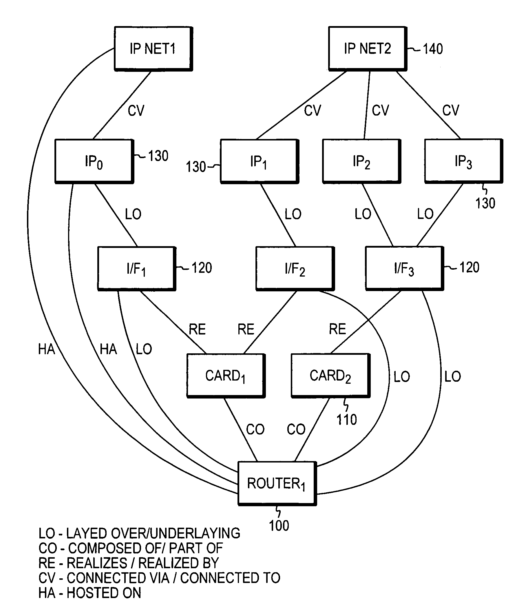
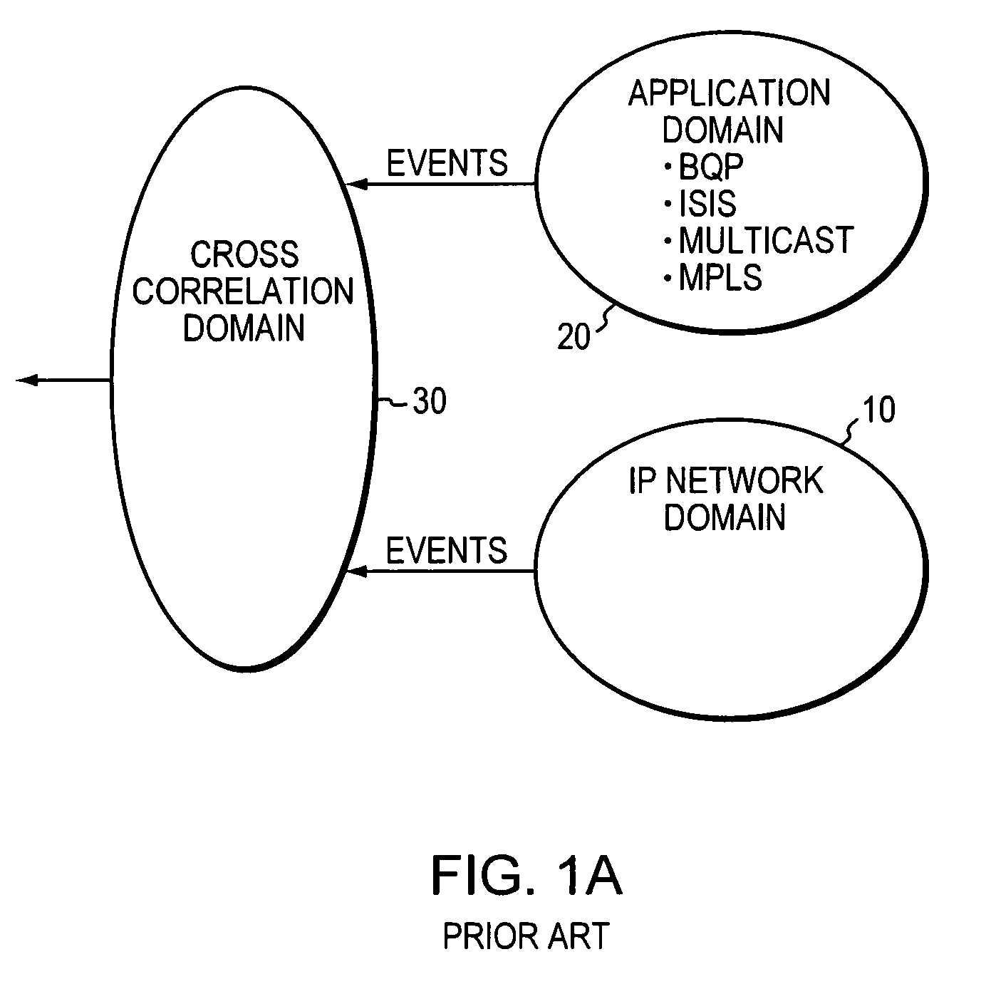
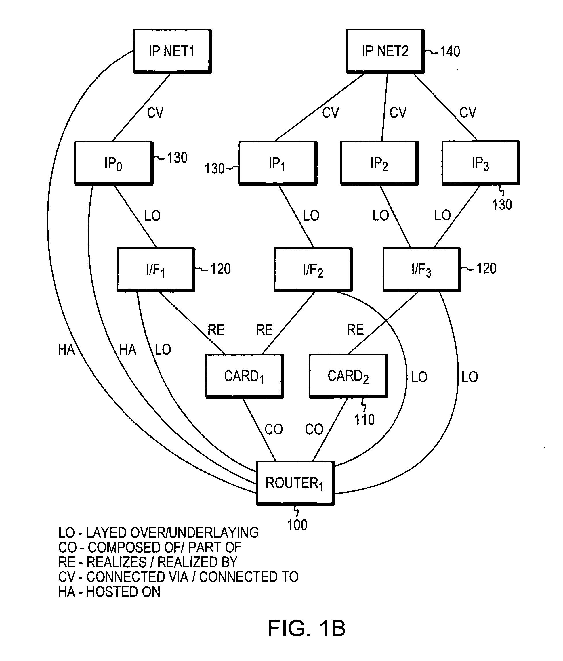
[0022]FIG. 1A illustrates an exemplary multi-domain model representation of a conventional network. Multi-domain modeling is advantageous as it allows for distribution of common elements and / or functions into individual domains and further allows for scalability as the size or the number of components in the network increases. In this illustrated representation shown, infrastructure elements of an IP network are grouped together and modeled in domain 10. These elements may constitute of hardware and software elements that represent the physical elements of the network. For example, the IP network elements may comprise hardware and software elements that are described in the well-known OSI stack physical layer (layer 1) and data link layer (layer 2). Similarly, applications which are operating on the underlying hardware and software are modeled and processed in domain 20. In this illustrated example, the application domain 20 comprises the elements in the protocol to the application ...


PUM


Abstract

A method, apparatus and computer-program product for performing a system analysis of a system is disclosed. The system is represented as a plurality of independent model domains, wherein the model domain represents selected ones of a plurality of components and the relationships among the components and the method comprises the steps of representing, as proxies, selected ones of the plurality of components of a first domain, wherein the relationships among the components are limited to direct relationships among adjacent ones of the components, wherein the first domain representation is available to a second domain, providing events occurring in the first domain to the second domain, providing a mapping between a plurality events and a plurality of observable events occurring among the proxy components of the first domain and a plurality of observable events occurring among the components of the second domain, wherein the mapping is represented as a value associating each event with each observable event, and performing the system analysis based on the mapping of events and observable events.

Description

[0001]A portion of the disclosure of this patent document contains command formats and other computer language listings, all of which are subject to copyright protection. The copyright owner, EMC Corporation, has no objection to the facsimile reproduction by anyone of the patent document or the patent disclosure, as it appears in the Patent and Trademark Office patent file or records, but otherwise reserves all copyright rights whatsoever.BACKGROUND[0002]This invention relates to the field of network modeling and more specifically to a simplified infrastructure modeling solution suitable for cross-domain processing.[0003]Computer modeling is well-known technique for representing systems. Using computer models it is possible to determine the performance characteristics or behavior of systems whether the system is actually built or is proposed. However, the results of computer models in capturing the performance characteristics or behavior of systems is dependent upon the model's accu...

Claims


Application Information

Patent Timeline
IPC IPC(8): G06G7/48G06G7/62
CPCG06F11/079G06F11/0748
Inventor VIJENDRA, SUDHIROU, CHAO-WEI
Owner VMWARE INC
Learn More