
Two-element f-theta lens used for micro-electro mechanical system (MEMS) laser scanning unit

a technology of laser scanning unit and micro-electro mechanical system, which is applied in the field of two-element f lenses, can solve the problems of increasing the number of components, increasing the manufacturing cost of lsu, and high difficulty of rotating polygon mirrors

Inactive Publication Date: 2009-11-17
E PIN OPTICAL IND
View PDF17 Cites 9 Cited by
  • Summary
  • Abstract
  • Description
  • Claims
  • Application Information

AI Technical Summary

Benefits of technology

[0013]The primary objective of the present invention is to overcome the shortcomings of the prior art by providing a two-element lens used for a micro-electro mechanical system (MEMS) laser scanning unit, the first lens is a biconvex lens and the second lens is a biconcave lens, which counted from the MEMS reflecting mirror, for projecting a scan light reflected by the MEMS reflecting mirror onto the correct image of a target to achieve a scanning linearity effect required by the laser scanning unit.
[0014]Another objective of the present invention is to provide a two-element fθ lens used for a micro-electro mechanical system (MEMS) laser scanning unit for reducing the area of a spot projected onto the target to achieve the effect of improving the resolution.
[0015]A further objective of the present invention is to provide a two-element fθ lens used for a MEMS laser scanning unit, and the two-element fθ lens can make a distortion correction to correct optical axis caused by the deviation of the scan light resulting in the problems of an increased deviation of the main scanning direction and the sub scanning direction, and a change of a spot of a drum at the image into an oval-like shape, and the two-element fθ lens can unify the size of each image spot to achieve the effect of enhancing the image quality.
[0017]The two-element fθ lens of the invention comprises a first lens and a second lens, counted from the MEMS reflecting mirror, wherein the first lens includes a first optical surface and a second optical surface, the second lens includes a third optical surface and a fourth optical surface. These optical surfaces provided the functions of correcting the phenomenon of non-uniform speed scanning which results in decreasing or increasing the distance between spots on an image surface of a MEMS reflecting mirror with a simple harmonic movement with time into a constant speed scanning, so that the projection of a laser beam onto an image side can give a constant speed scanning, and unify the deviation of image formed on the drum which caused by a scan light in the main scanning direction and the sub scanning direction deviated from the optical axis, so as to make a correction to focus the scan light at a target.

Problems solved by technology

However, the traditional laser scanning unit (LSU) still has the following drawbacks in its practical use.
(1) The manufacture of the rotating polygon mirror incurs a high level of difficulty and a high cost, and thus increasing the manufacturing cost of the LSU.
Such arrangement increases the number of components and also complicates the assembling operation procedure.
(3) The traditional polygon mirror requires a high-speed rotation (such as 40000 rpm), and thus the noise level is raised.
Furthermore, the polygon mirror takes a longer time to be accelerated from a starting speed to an operating speed, and thus increasing the booting time of the laser scanning.
(4) In the fabrication of the traditional LSU, the central axis of a laser beam projected onto the reflecting mirror of the polygon mirror is not aligned precisely with the central rotating axis of the polygon mirror, so that it is necessary to take the off axis deviation of the polygon mirror into consideration for the design of the fθ lens, and thus increasing the difficulty of design and manufacturing the fθ lens.
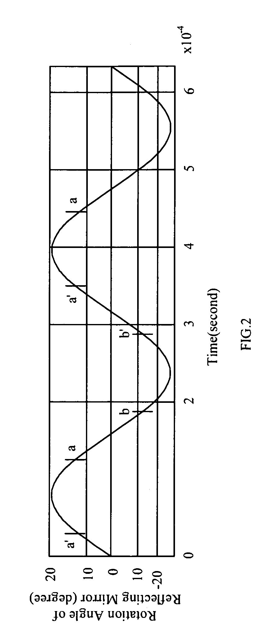
Since the angle of the MEMS reflecting mirror situated at a peak and a valley of a sine wave varies with time, and the rotating movements if a traditional polygon mirror are at a constant angular speed, if a traditional fθ lens is installed on a laser scanning unit (LSU) of the MEMS reflecting mirror, the angle of the MEMS reflecting mirror produced by the sinusoidal relation varied with time cannot be corrected, so that the speed of laser beam projected on an image side will not be an uniform speed, and the image on the image side will be deviated.
However, the laser light beam is essential an oval-like shape of the cross section that corrects the scan lights in the main-scanning direction only may not be achieve the accuracy requirement.

Method used


Image

  • Two-element f-theta lens used for micro-electro mechanical system (MEMS) laser scanning unit
  • Two-element f-theta lens used for micro-electro mechanical system (MEMS) laser scanning unit
  • Two-element f-theta lens used for micro-electro mechanical system (MEMS) laser scanning unit

Examples


Embodiment Construction

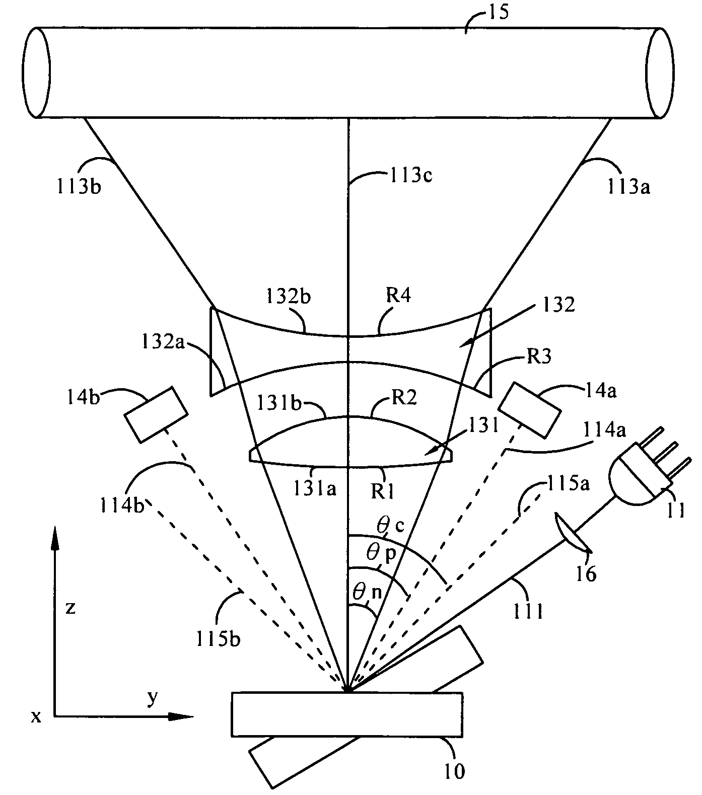
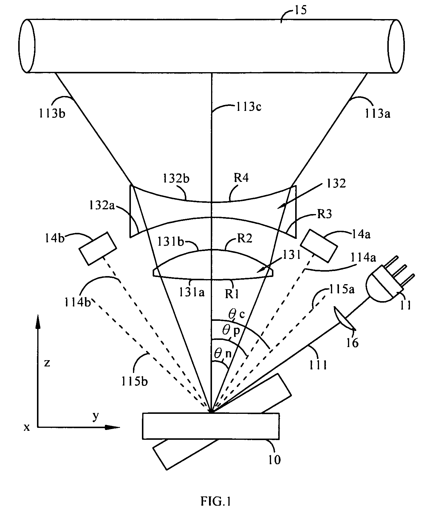
[0029]Referring to FIG. 1 for a schematic view of optical paths of a two-element fθ lens used for micro-electro mechanical system (MEMS) laser scanning unit in accordance with the present invention, the two-element fθ lens used for the micro-electro mechanical system (MEMS) laser scanning unit 13 comprises: a first lens 131 having a first optical surface 131a and a second optical surface 131b, and a second lens 132 having a third optical surface 132a and a fourth optical surface 132b. In FIG. 1, the MEMS laser scanning unit comprises a laser source 11, a MEMS reflecting mirror 10, a cylindrical lens 16, two photoelectric sensors 14a, 14b, and a light sensing target. In FIG. 1, the target is implemented by a drum 15. After a beam 111 produced by the light laser source 11 is passed through a cylindrical lens 16, the beam 111 is projected onto the MEMS reflecting mirror 10. The MEMS reflecting mirror 10 generates a resonant oscillation to reflect the beam 111 into scan lights 113a, 113...


PUM


Abstract

A two-element f-θ lens used for a micro-electro mechanical system (MEMS) laser scanning unit includes a first lens and a second lens, the first lens is a biconvex lens and the second lens is a biconcave lens. At least one optical surface is aspherical surface in both main scanning direction and sub scanning direction, and satisfies special optical conditions. The two-element f-θ lens corrects the nonlinear relationship between scanned angle and the time into the linear relationship between the image spot distances and the time. Meanwhile, the two-element f-θ lens focuses the scan light to the target in the main scanning and sun scanning directions, such that the purpose of the scanning linearity effect and the high resolution scanning can be achieved.

Description

BACKGROUND OF THE INVENTION[0001]1. Field of the Invention[0002]The present invention relates to a two-element fθ lens used for a micro-electro mechanical system (MEMS) laser scanning unit (LSU), and more particularly to a two-element fθ lens using an angular change varying with time in a sinusoidal relation for correcting a MEMS reflecting mirror having a simple harmonic movement to achieve the scanning linearity effect required by the laser scanning unit.[0003]2. Description of the Related Art[0004]At present, a laser scanning unit (LSU) used by a laser beam printer (LBP) controls a laser beam scanning by a high-speed rotating polygon mirror as disclosed in U.S. Pat. Nos. 7,079,171, 6,377,293 and 6,295,116 or TW Pat No. I198966, and principles of those inventions are described as the following: a semiconductor laser emits a laser beam through a collimator and an aperture to form parallel beams. After the parallel beams pass through a cylindrical lens, the beams are focused at the ...

Claims


Application Information

Patent Timeline
IPC IPC(8): G02B26/08
CPCG02B26/105
Inventor SHIH, BO-YUANSHYU, SAN-WOEI
Owner E PIN OPTICAL IND
Learn More