
Passive radar utilizing space-borne digital electromagnetic illuminators

a technology of digital electromagnetic illuminators and passive radars, applied in the field of radar systems, can solve the problems of low effective radiated power, operator's inability to control the availability of illuminators, and reliance on third-party transmitters

Inactive Publication Date: 2009-11-17
SHKLARSKY DAN ABRAHAM
View PDF4 Cites 15 Cited by
  • Summary
  • Abstract
  • Description
  • Claims
  • Application Information

AI Technical Summary

Benefits of technology

Enables effective three-dimensional imaging, moving target detection, and identification, improving signal-to-noise ratios and expanding operational capabilities beyond traditional passive radar limitations by leveraging multiple satellite transmitters for diversity imaging and stereoscopic depth measurement.

Problems solved by technology

Disadvantages of passive radar include a reliance on third-party transmitters, the operator having no control over the availability of the illuminator, and low effective radiated power.

Method used


Image

  • Passive radar utilizing space-borne digital electromagnetic illuminators
  • Passive radar utilizing space-borne digital electromagnetic illuminators
  • Passive radar utilizing space-borne digital electromagnetic illuminators

Examples


examples

2.1 SAR

Cooled T<400 k;

Un-cooled T<600 k;

Assuming

[0083]sas0≈1

we get:

[0084]vt*R*(S⁢ / ⁢N)σ<C1={108⁢(cooled);⁢7*107⁢(un⁢-⁢cooled);

Detection by Fixed System (Radial Constant Mutual Velocity):

Radial movements are processed by simple Doppler processing. in this case the duration of a target within each range bin must be longer than the duration of the essential coherent integration. The width of a range bin is given by:

[0085]δ⁢⁢r≈c2*W0

The radial component of the velocity is vr and the transition time is:

[0086]Tt=δ⁢⁢rvr=c2*W0*vr

Resulting in a condition on maximal velocity:

[0087]T≤c2*W0*vr=Ttorvr≤c2*QD;

The coherent processing gain is calculated as before according to:

[0088]QD=2*π*k*TI*SN*ɛeσt*θ2;

And after some manipulations:

[0089]vr*R2σ<c*I*sa*ɛe2*π*k*T*SN

2.3. Fixed Ground System (Un-Cooled)

The calculation here is done as follows: QD is determined from the ratio c / v, QD and the wanted S / N dictates the minimal possible 0 to calculate maximal range Rmax

Antenna of 1 sq.m, S / N=6 db:

Maximal...


PUM


Abstract

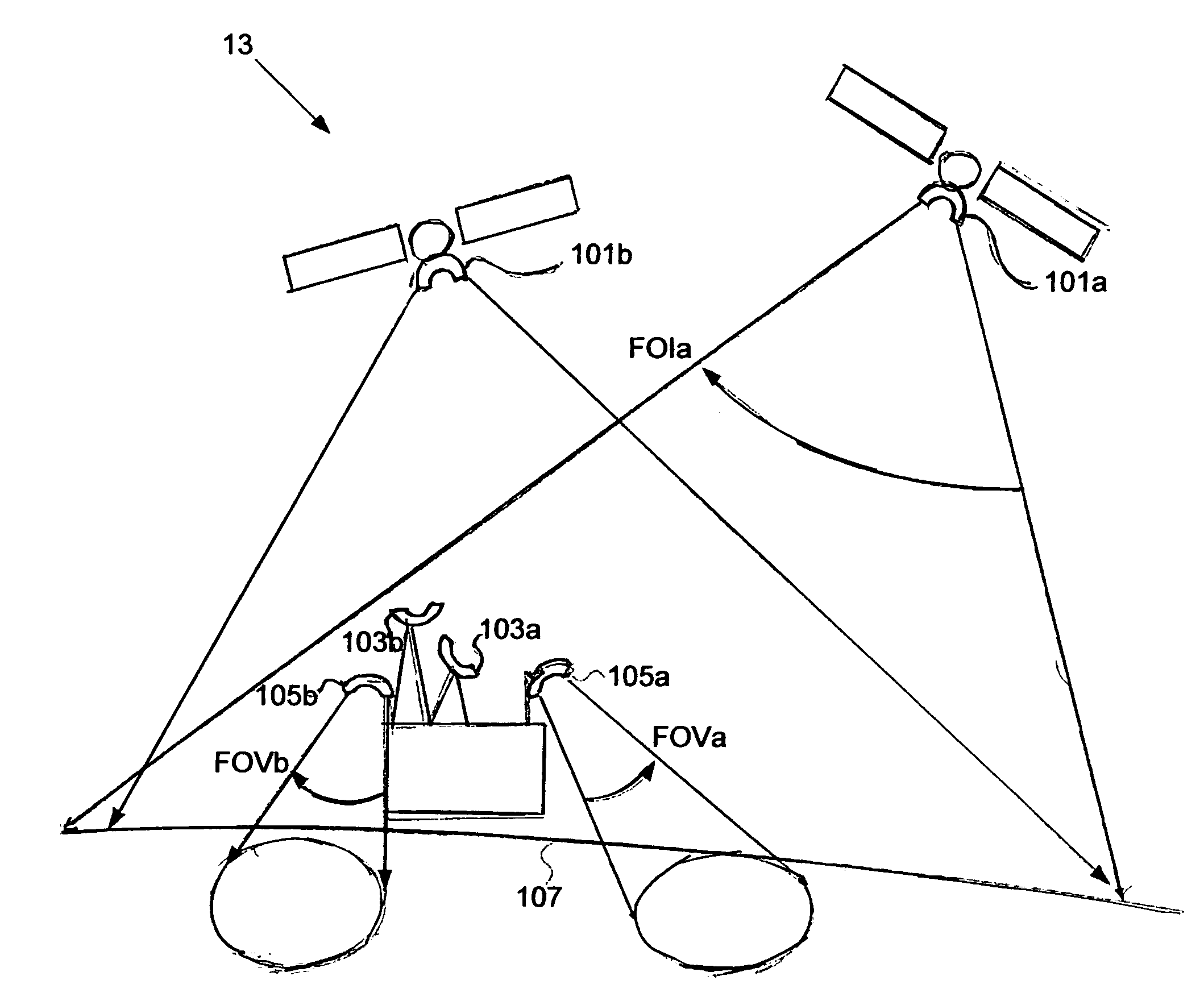
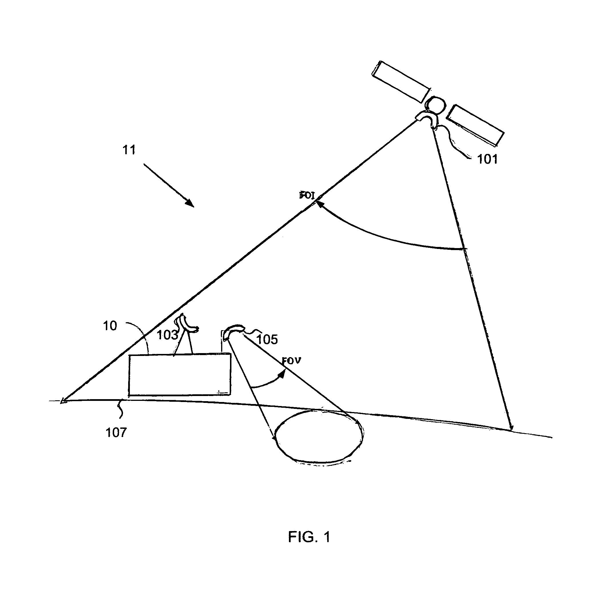
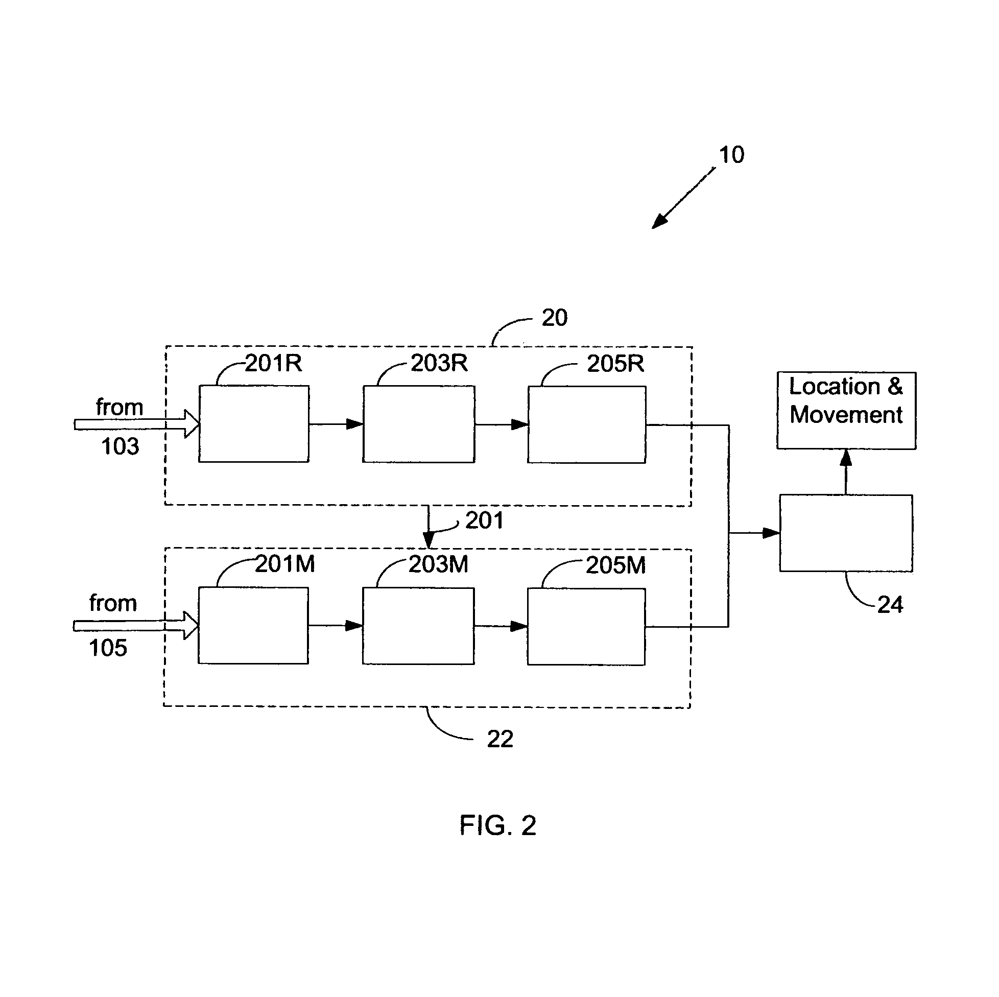
In a passive radar system a space-borne transmitter broadcasts wide-band digitally modulated signals over a region and illuminates the region. A receiver antenna is oriented to receive radiation from at least one portion of the region. The portion is an area viewed by the receiver antenna. A reference antenna is oriented toward the transmitter, the reference antenna receives a portion of the wide-band digitally modulated signal. A coherent processing time duration is selected based on: a radar cross-section of a target within the viewed area, a bandwidth of the wide-band digitally modulated signal, and the viewing angle of the receiver antenna. The received signal from the receiver antenna is coherently processed with a reference signal from the reference antenna, over a time interval greater than the coherent processing time duration.

Description

TECHNICAL FIELD[0001]The present invention relates generally to radar systems and more specifically to passive radar utilizing space-borne radiators of wide-band electromagnetic radiation as illuminators.BACKGROUND OF THE INVENTION[0002]Commonly radar systems are active with a dedicated radio transmitter and a dedicated receiver. Passive radar systems do not have dedicated transmitters but use electromagnetic illumination available from external sources. A bistatic radar uses a single spatially separated transmitter and a single receiver. A multistatic configuration includes multiple transmitters and receivers. In passive radar, a signal reflected or scattered from an object is correlated with the signal originating at the transmitter as a reference signal.[0003]Passive radar has several benefits including low costs of operation and maintenance, and an ability to operate covertly and non-intrusively. Hence, passive radar may be deployed in areas where normal radars cannot be deploye...

Claims


Application Information

Patent Timeline
Patent Type & Authority Patents(United States)
IPC IPC(8): G01S13/90
CPCG01S13/003G01S13/0209
Inventor SHKLARSKY, DAN ABRAHAM
Owner SHKLARSKY DAN ABRAHAM
Learn More