Exhaust emission control device and method for internal combustion engine, and engine control unit

a technology of exhaust emission control and control device, which is applied in flow control, special data processing applications, boron compounds, etc., can solve the problems of degrading fuel economy, increasing exhaust emissions, and reducing fuel economy, so as to reduce the amount of agent consumption. calculating, the effect of reducing the amount of agent consumption

Inactive Publication Date: 2009-11-17
HONDA MOTOR CO LTD
View PDF5 Cites 2 Cited by
  • Summary
  • Abstract
  • Description
  • Claims
  • Application Information

AI Technical Summary

Benefits of technology

[0020]With the configuration of the second aspect of the present invention, it is possible to obtain the same advantageous effects as provided by the first aspect of the present invention.
[0021]Preferably, the engine includes an air-fuel ratio-detecting means disposed in the exhaust passage at a location upstream of the upstream catalyst, for detecting an air-fuel ratio of the exhaust gases in the exhaust passage as an actual air-fuel ratio, and the reducing agent consumption amount-calculating step include calculating the reducing agent consumption amount according to the actual air-fuel ratio.
[0022]More preferably, the reducing agent consumption amount-calculating step includes switching methods for calculating the reducing agent consumption amount according to a result of comparison between the actual air-fuel ratio and the predetermined value.
[0023]Preferably, the reducing agent consumption amount-calculating step further comprises an oxygen storage amount-calculating step of calculating an amount of oxygen stored in the upstream catalyst as an oxygen storage amount, and includes calculating the reducing agent consumption amount such that the reducing agent consumption amount takes a larger value as the calculated oxygen storage amount is larger.
[0024]Preferably, the reducing agent consumption amount-calculating step further comprises a degradation degree-calculating step of calculating a degree of degradation of the upstream catalyst, and a correction step of correcting the reducing agent consumption amount depending on the calculated degree of degradation.
[0025]With the configurations of these preferred embodiments, it is possible to obtain the same advantageous effects as provided by the respective corresponding preferred embodiments of the first aspect of the present invention.

Problems solved by technology

In this case, the exhaust emission control device calculates the cumulative value S_QDA of the amount of reducing agent based on the signal from the air-fuel ratio sensor upstream of the three-way catalyst, and hence the calculation accuracy of the cumulative value S_QDA is lowered due to consumption of the reducing agent by the oxygen stored in the three-way catalyst, which can cause improper timing for terminating the rich spike control.
This causes the concentrations of HC and CO in exhaust gases to be held high, resulting in increased exhaust emissions and degraded fuel economy.
Inversely, when the timing for terminating the rich spike control is earlier than the timing in which the NOx reducing operation of the NOx catalyst is terminated, NOx trapped in the NOx catalyst is not sufficiently reduced, which causes insufficient NOx trapping performance of the NOx catalyst, resulting in increased exhaust emissions.

Method used


Image

  • Exhaust emission control device and method for internal combustion engine, and engine control unit
  • Exhaust emission control device and method for internal combustion engine, and engine control unit
  • Exhaust emission control device and method for internal combustion engine, and engine control unit

Examples


Embodiment Construction

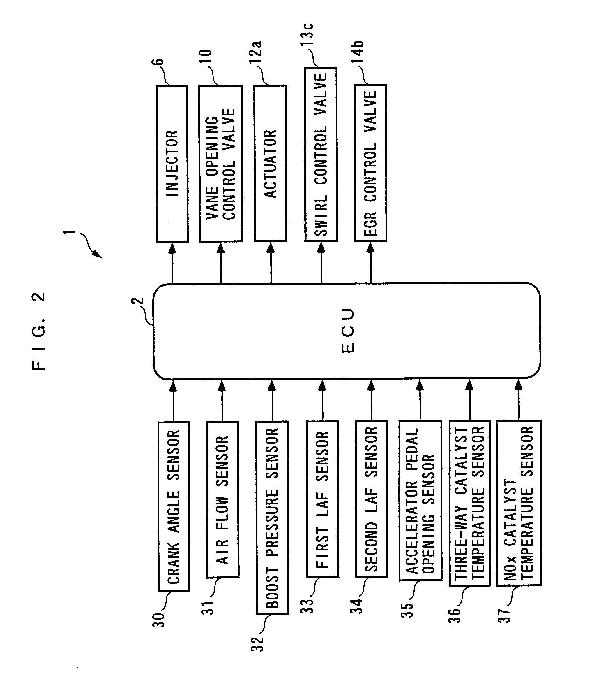
[0048]Hereafter, an exhaust emission control device according to an embodiment of the present invention will be described with reference to the drawings. FIG. 1 is a diagram showing the exhaust emission control device 1 according to the present embodiment and an internal combustion engine (hereinafter simply referred to as “the engine”) 3 to which is applied the exhaust emission control device 1. As shown in FIG. 2, the exhaust emission control device 1 includes an ECU 2. As described hereinafter, the ECU 2 carries out various control processes, such as an air-fuel ratio control process, depending on operating conditions of the engine 3.

[0049]The engine 3 is an in-line four-cylinder diesel engine that includes a four pairs of cylinders and pistons 3a (only one pair of which is shown), and is installed on a vehicle, not shown. A combustion chamber 3c is defined between a piston 3a and a cylinder head 3b for each cylinder of the engine 3. The cylinder head 3b has an intake pipe 4 and ...


PUM

PropertyMeasurementUnit
crank angleaaaaaaaaaa
temperatureaaaaaaaaaa
concentrationsaaaaaaaaaa

Abstract

An exhaust emission control device for an internal combustion engine, which is capable of supplying a just enough amount of reducing agent to a NOx catalyst, thereby reducing exhaust emission and improving fuel economy. The device includes a three-way catalyst, a NOx catalyst provided downstream of the three-way catalyst, and an ECU. The ECU carries out rich spike control such that exhaust gases flowing into the NOx catalyst form a reducing atmosphere. During the control, the ECU calculates a reducing agent consumption amount of reducing agent in the exhaust gases consumed by the three-way catalyst, calculates a cumulative reducing agent amount as a total amount of reducing agent supplied to the NOx catalyst, depending on the reducing agent consumption amount, and terminates the control when the cumulative reducing agent amount becomes larger than a predetermined value.

Description

BACKGROUND OF THE INVENTION[0001]1. Field of the Invention[0002]The present invention relates to an exhaust emission control device and method for an internal combustion engine, including an exhaust passage, a NOx catalyst disposed in the exhaust passage for reducing trapped NOx in a reducing atmosphere, and a catalyst which is disposed at a location upstream of the NOx catalyst and has an oxidation function, and an engine control unit, the engine the exhaust emission control device and method and the engine control unit causing reducing agent to be supplied to the upstream side of the catalyst, so as to cause the NOx catalyst to carry out a NOx reducing operation.[0003]2. Description of the Related Art[0004]Conventionally, as an exhaust emission control device of this kind, the present assignee has already proposed an exhaust emission control device disclosed in Japanese Laid-Open Patent Publication (Kokai) No. 2006-207487. This exhaust emission control device is applied to a diese...

Claims


Application Information

Patent Timeline
Patent Type & Authority Patents(United States)
IPC IPC(8): B01D53/56B01D53/94F01N3/10F01N3/18
CPCB01D53/9409F01N13/009F01N3/0814F01N3/0842F01N3/0871F01N3/106F02D41/0275F02D41/1462B01D53/9495B01D2251/20F01N2560/025F01N2560/06F01N2560/14F01N2900/08F01N2900/1402F01N2900/1621F01N2900/1622F02B37/00F02D2200/0806Y02C20/10Y10S423/05
Inventor MORITA, TOMOKOSUZUKI, NORIOOHNO, HIROSHI
Owner HONDA MOTOR CO LTD
Why Eureka
Try Eureka