
Reaction chamber for manufacturing a carbon nanotube, apparatus for manufacturing the carbon nanotube and system for manufacturing the carbon nanotube

a technology of carbon nanotubes and reaction chambers, which is applied in the field of reaction chambers apparatus system for manufacturing carbon nanotubes, can solve the problems of thermal damage, deterioration of conventional apparatus, and relatively reduced space of reaction tubes b>1/b> for forming carbon nanotubes, etc., to achieve enhanced efficiency of each reaction chamber, apparatus and system, and improved carbon nanotube purity

Active Publication Date: 2009-11-17
SEMES CO LTD
View PDF11 Cites 28 Cited by
  • Summary
  • Abstract
  • Description
  • Claims
  • Application Information

AI Technical Summary

Benefits of technology

The present invention provides a reaction chamber for manufacturing carbon nanotubes with a high purity and a high spatial and production efficiency. The reaction chamber includes a reaction furnace with a gas inlet, gas outlet, and heat transfer member. The gas inlet and gas outlet are opposite each other, and the heat transfer member has at least one rectangular through-hole structure formed at a third portion of the reaction furnace along a direction parallel to the substrate. The gas inlet and gas outlet may be connected to a gas supply member and a gas exhausting member, respectively. The heating member may face with the heat transfer member to provide heat into the reaction furnace. The reaction furnace may have a opening and closing member for loading and unloading the substrate. The apparatus for manufacturing carbon nanotubes includes the reaction chamber, gas supply member, and heating member. The technical effects of the present invention include high purity and high efficiency of carbon nanotube production.

Problems solved by technology

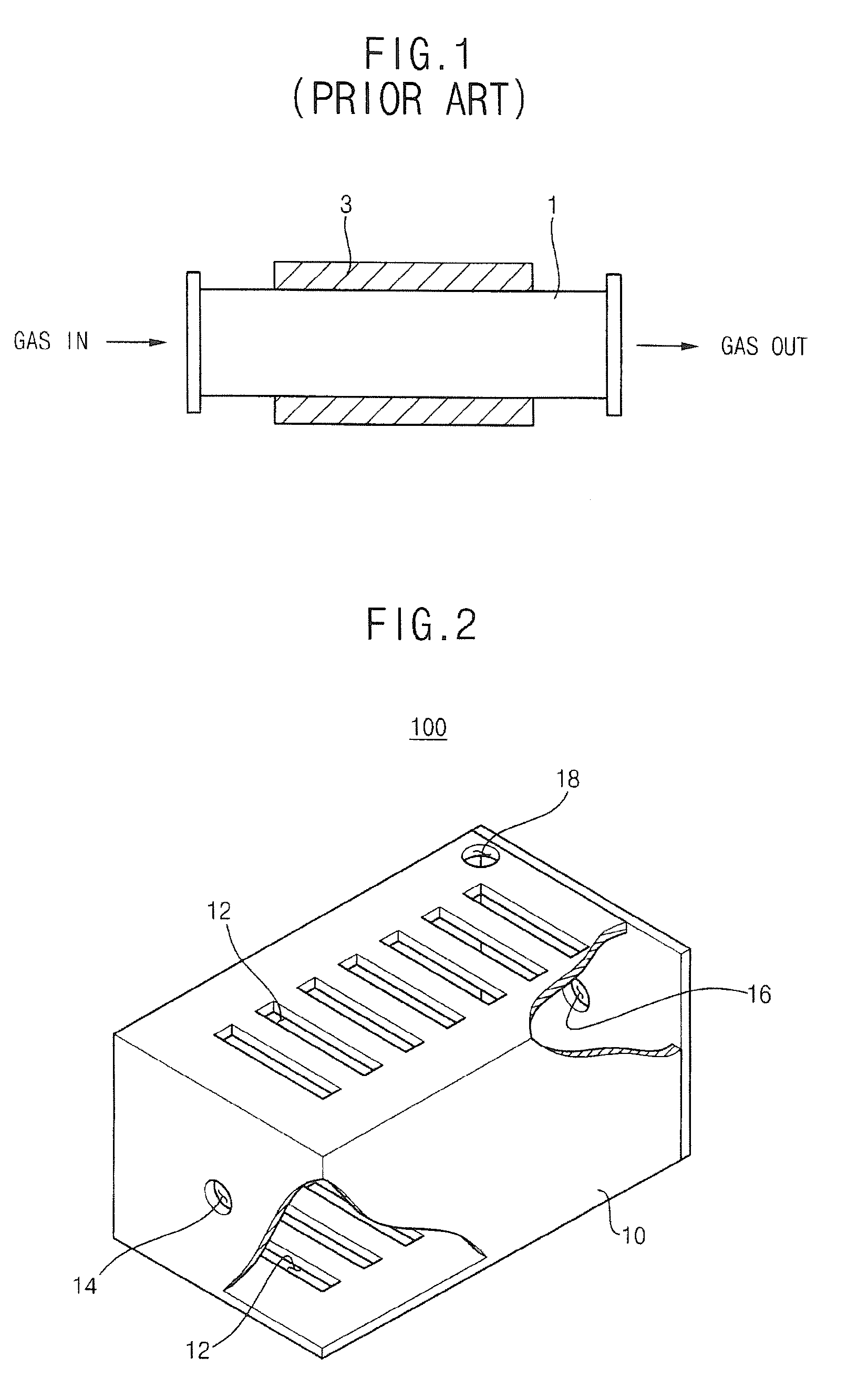
In the conventional apparatus for manufacturing the carbon nanotube, however, the heating member 3 partially encloses the reaction tube 1 because other elements of the conventional apparatus may have thermal damages when the heating member 3 entirely encloses the reaction tube 1.
Hence, a space of the reaction tube 1 for forming the carbon nanotube may be relatively reduced and an efficiency of the conventional apparatus may be deteriorated.
Additionally, the gas may not be uniformly provided into the reaction tube 1 to deteriorate a purity of the carbon nanotube because the gas passes through relatively wide portions in the reaction tube 1 until the gas reaches at the substrate positioned in a space of the reaction tube 1 for forming the carbon nanotube.
The carbon nanotube manufactured using the conventional apparatus may have a poor purity, and the conventional apparatus may not advantageously employed in high-volume manufacturing since the efficiency of the conventional apparatus is reduced and the gas is not uniformly provided onto the substrate.
Furthermore, the heating member 3 directly heats the reaction tube 1 of the conventional apparatus such that a durability of the reaction tube 1 may be considerably deteriorated.

Method used


Image

  • Reaction chamber for manufacturing a carbon nanotube, apparatus for manufacturing the carbon nanotube and system for manufacturing the carbon nanotube
  • Reaction chamber for manufacturing a carbon nanotube, apparatus for manufacturing the carbon nanotube and system for manufacturing the carbon nanotube
  • Reaction chamber for manufacturing a carbon nanotube, apparatus for manufacturing the carbon nanotube and system for manufacturing the carbon nanotube

Examples


Embodiment Construction

[0051]The present invention is described more fully hereinafter with reference to the accompanying drawings, in which example embodiments of the present invention are shown. The present invention may, however, be embodied in many different forms and should not be construed as limited to the example embodiments set forth herein. Rather, these embodiments are provided so that this disclosure will be thorough and complete, and will fully convey the scope of the present invention to those skilled in the art. In the drawings, the sizes and relative sizes of layers and regions may be exaggerated for clarity.

[0052]It will be understood that when an element or layer is referred to as being “on,”“connected to” or “coupled to” another element or layer, it can be directly on, connected or coupled to the other element or layer or intervening elements or layers may be present. In contrast, when an element is referred to as being “directly on,”“directly connected to” or “directly coupled to” anot...


PUM

PropertyMeasurementUnit
temperatureaaaaaaaaaa
pressureaaaaaaaaaa

Abstract

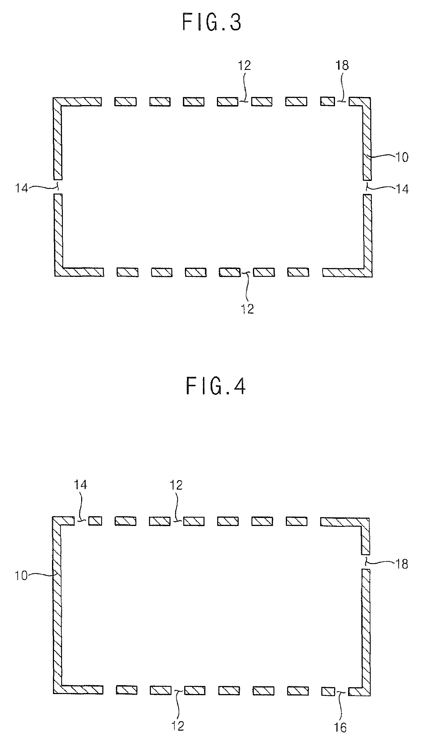
Disclosed are a reaction chamber for manufacturing a carbon nanotube, an apparatus for manufacturing a carbon nanotube and a system for manufacturing a carbon nanotube. The reaction chamber includes a reaction furnace, a gas inlet, a gas outlet and a heat transfer member. The reaction furnace has a box structure for receiving a substrate wherein the reaction furnace provides a space for forming the carbon nanotube on the substrate. The gas inlet having a through-hole structure formed at a first portion of the reaction furnace and the gas outlet has a through-hole structure formed at a second portion of the reaction furnace. The heat transfer member has at least one rectangular through-hole structure formed at a third portion of the reaction furnace along a direction substantially in parallel to the substrate. The apparatus includes the reaction furnace, a gas supply member, a gas exhausting member and a heating member. The system includes the apparatus and a transfer apparatus.

Description

CROSS-REFERENCE TO RELATED APPLICATION[0001]This application claims priority under 35 USC §119 to Korean Patent Application No. 2006-131459 filed on Dec. 21, 2006, the contents of which are herein incorporated by references in their entirety.BACKGROUND OF THE INVENTION[0002]1. Field of the Invention[0003]Example embodiments of the present invention relate to a reaction chamber for manufacturing a carbon nanotube, an apparatus for manufacturing the carbon nanotube, and a system for manufacturing the carbon nanotube. More particularly, example embodiments of the present invention relate to a reaction chamber for manufacturing a carbon nanotube having a high purity at a high temperature, an apparatus having the reaction chamber for manufacturing the carbon nanotube, and a system including the reaction chamber for manufacturing the carbon nanotube.[0004]2. Description of the Related Art[0005]A carbon nanotube as an allotrope of carbon may have a crystalline structure in which carbon ato...

Claims


Application Information

Patent Timeline
Patent Type & Authority Patents(United States)
IPC IPC(8): B01J8/00B01J8/02C01B31/02C23C16/00D01F9/12
CPCB01J6/00C01B31/0233B01J19/2445B01J19/248B82Y30/00B82Y40/00B01J19/24B01J2219/00038B01J2219/0009B01J2219/00135B01J2219/00139B01J2219/00146B01J2219/00162B01J2219/00164B01J2219/182B01J2219/1923B01J2219/1943C01B32/162Y10S977/842Y10S977/843Y10S977/855
Inventor KIM, SUNG-SOOJEON, JONG-KWAN
Owner SEMES CO LTD
Learn More