
Image enhancement by spatial linear deconvolution

a spatial linear deconvolution and enhancement technology, applied in image enhancement, instruments, analogue processes for specific applications, etc., can solve the problem of quite significant computation cos

Active Publication Date: 2009-11-10
RES FOUND OF STATE OF UNIV OF NEW YORK THE
View PDF12 Cites 7 Cited by
  • Summary
  • Abstract
  • Description
  • Claims
  • Application Information

AI Technical Summary

Benefits of technology

The linear filter technique effectively reduces blurring effects, improving image resolution and accuracy, and is applicable to various physical and mathematical systems with non-linear relationships, offering a more efficient alternative to traditional non-linear methods.

Problems solved by technology

The problem is to determine the optical properties of the medium based on the detected energy.
While this approach can yield good results, the computational expense is quite significant.

Method used


Image

  • Image enhancement by spatial linear deconvolution
  • Image enhancement by spatial linear deconvolution
  • Image enhancement by spatial linear deconvolution

Examples


example imaging

System

[0049]FIG. 6 illustrates an example imaging system, shown generally at 600. A system providing high speed data capture of one or more wavelengths simultaneously from a target medium using optical tomography is disclosed in PCT publication WO 01 / 020306, published Mar. 22, 2001, and entitled “System And Method For Tomographic Imaging Of Dynamic Properties Of A Scattering Medium”, incorporated herein by reference. This system is capable of capturing multiple wavelength data at rates up to 150 Hz and enables the reconstruction of cross-sectional images of real-time events associated with vascular reactivity in a variety of tissue structures (e.g., limbs, breast, head and neck). Fast data collection methods are particularly useful because there are many disease states with specific influences on the spatial-dynamic properties of vascular responses in hemoglobin states.

[0050]The system 600 includes a computer control and data storage component 602. This component can be provided by ...


PUM


Abstract

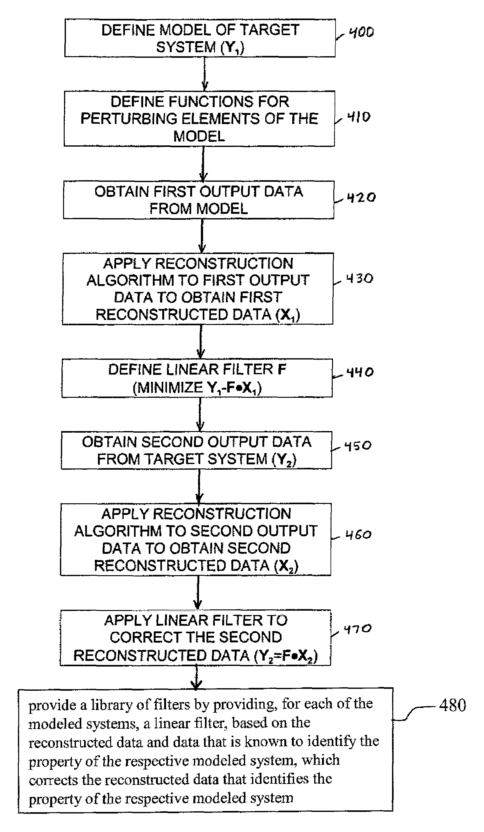
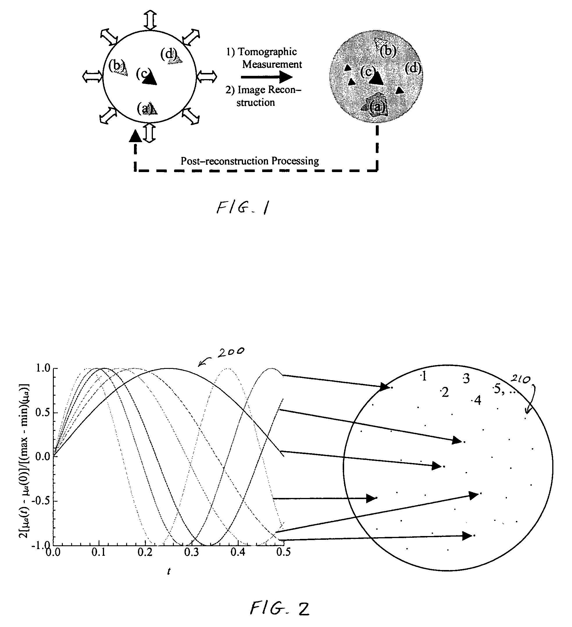
Data from a target system (616) that exhibits a non-linear relationship between system properties and measurement data, is processed by applying a linear filter (F) to improve resolution and accuracy. The filter reduces inaccuracies that are introduced by an algorithm used to reconstruct the data. The filter is defined by assigning time varying functions, such as sinusoids (200), to elements (210) in a model (Y) of the system to perturbate the elements. The resulting data output from the model is reconstructed using the same algorithm used to subsequently reconstruct the data from the target system. The filter is defined as a matrix (F) that transforms the reconstructed data of the model (X) back toward the known properties of the model (Y). A library of filters can be pre-calculated for different applications. In an example implementation, the system is tissue that is imaged using optical tomography.

Description

CROSS-REFERENCE TO RELATED APPLICATIONS[0001]This application claims the benefit of U.S. provisional patent application Ser. No. 60 / 488,325, filed Jul. 18, 2003, and incorporated herein by reference.STATEMENT REGARDING FEDERALLY SPONSORED RESEARCH OR DEVELOPMENT[0002]This invention was made with government support under grants 5R01CA66184, 1R21DK63692 and 5R21HL67387. The government has certain rights in the invention.BACKGROUND OF THE INVENTION[0003]1. Field of Invention[0004]The invention relates generally to a technique for correcting data obtained from a system, for which measurements obtained from the system are nonlinear functions of its interior properties, to remove blurring effects that are introduced during reconstruction processing of the data. In a particular implementation, the invention relates to deblurring of image data obtained using optical diffusion tomography.[0005]2. Description of Related Art[0006]Various techniques have been developed for processing data in im...

Claims


Application Information

Patent Timeline
Patent Type & Authority Patents(United States)
IPC IPC(8): G06F7/60G06F17/10A61B
CPCG06T5/003G06T2207/10101G06T2207/30004G06T5/73
Inventor BARBOUR, RANDALL L.GRABER, HARRY L.PEI, YALINGXU, YONG
Owner RES FOUND OF STATE OF UNIV OF NEW YORK THE
Learn More