
Energy conversion apparatus for wheeled vehicles

a technology of energy conversion apparatus and wheel drive, which is applied in the direction of electric propulsion mounting, wheel attachment, transportation and packaging, etc., can solve the problems of large energy loss after multiple transmissions, large impact force generated by the rotation of the wheel drive, and complex structure, etc., and achieves simple structure, energy extraction and conversion, low manufacturing and assembly

Inactive Publication Date: 2009-11-10
YANG XIAOLI
View PDF6 Cites 20 Cited by
  • Summary
  • Abstract
  • Description
  • Claims
  • Application Information

AI Technical Summary

Benefits of technology

[0010]One objective of the invention is to overcome the above-described disadvantages, and provide an apparatus for extracting and converting energy using hydraulic fluid at high pressure common to all wheels that features simple structure, low manufacturing cost and assembly requirement, and good interchangeability between wheels having similar specification.
[0029]Advantages provided by the invention are as follows. The invention is capable of making use of the weight of a vehicle to extract and convert energy. Compared with the prior art, the embodiments of the invention have a simple structure and low manufacturing and assembling requirement, may be used directly as a wheel, do not require the traditional inflatable inner tube, combine and provide output hydraulic fluid at high pressure from all wheels to the hydraulic motor, and features good interchangeability between wheels having similar specification.
[0030]Taking a gas-powered vehicle as an example, by utilizing the output hydraulic fluid at high pressure to drive a hydraulic motor, fuel savings of 45-60% may be realized. The hydraulic fluid circulates in the wheel and no complex rotary seal is needed, which greatly improve operating reliability and allow for application of the invention to high-speed wheels. Specifically, embodiments of the invention are applicable to vehicles such as cars, trucks, bicycles, and so on. The energy saving rate is proportional to speed.

Problems solved by technology

However, the impact force generated by the rotation of the wheels is too small to be of practical use.
The structure is complex and energy losses after multiple transmissions are significant.
Moreover, it is difficult to attain a high-speed reciprocating movement of the pistons, and especially a simultaneous movement of two cylinders, and therefore the overall energy recovery is relatively low.
Finally, the inclined position of the hydraulic fluid reservoir leads to a decreased balance during rotation of the wheel, and a large number of interconnected pipes reduces reliability.
However, since the device uses an external hydraulic fluid-reservoir and extra pipes are connected to an annular hydraulic strengthener, the solution is relatively complex, the number of accessories is large, the reliability is poor, and the loss of hydraulic fluid is great.
Moreover, the backward push of the wheel by the cylinder not only makes the structure complex, but also does not allow for a high-speed transfer.
Finally, the externally-connected hydraulic fluid pump consumes relatively high-amount of energy.
In sum, conventional annularly-arranged hydraulic cylinder devices generate hydraulic fluid pressure by compressing a hydraulic plunger during the rotation of wheels, drive hydraulic components, so as to extract energy and apply driving force to rotating wheels whenever necessary, but have the disadvantages such as complex structure, difficult applicability to multiple wheels, and high manufacturing and assembly cost.
In addition, the cost requirement of externally-disposed hydraulic fluid reservoir is comparatively high, and multiple rotary seals are needed.

Method used


Image

  • Energy conversion apparatus for wheeled vehicles
  • Energy conversion apparatus for wheeled vehicles
  • Energy conversion apparatus for wheeled vehicles

Examples


example 1

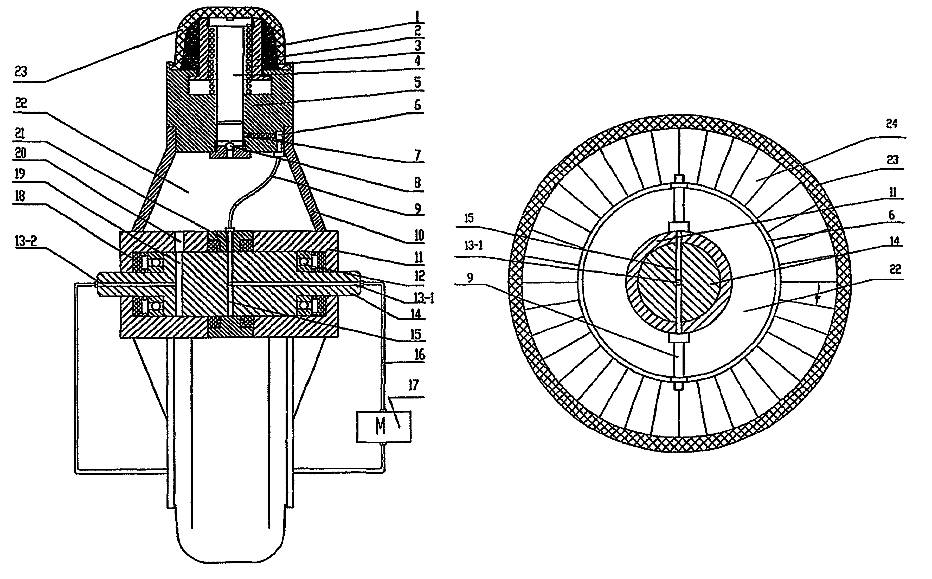
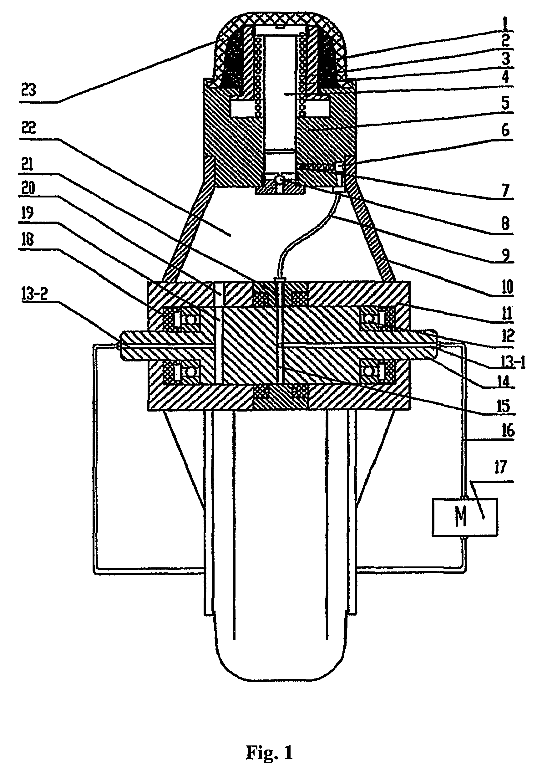
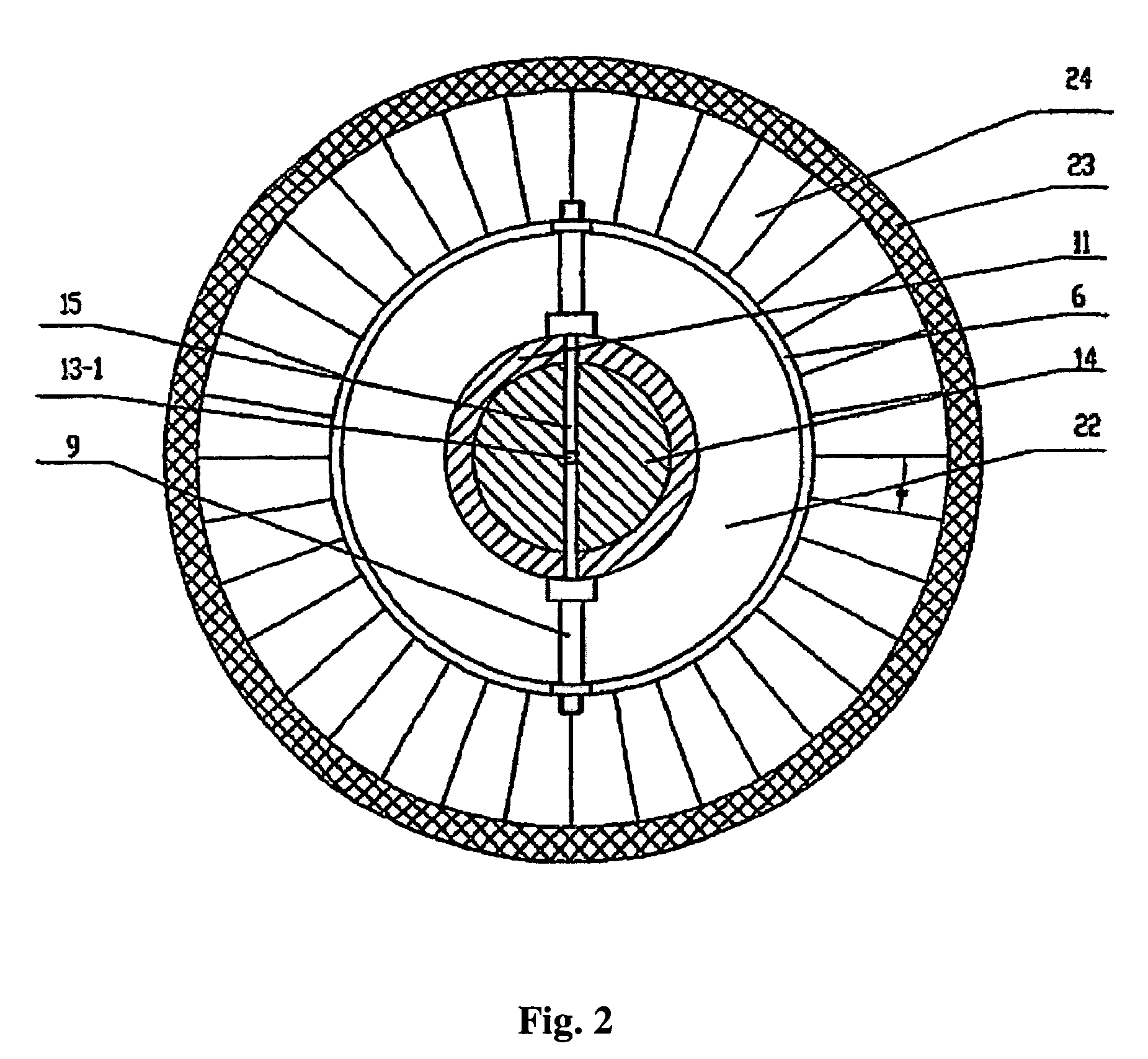
[0036]Referring to FIGS. 1 and 2, in an energy conversion apparatus for wheeled vehicles, a wheel rim comprises a plurality of peripheral annular cylinder blocks 5, a rotary shaft sleeve is disposed on the center comprising a rotary shaft sleeve 11 and a central axis 14, and a closed annular hydraulic fluid reservoir 22 is disposed therebetween and surrounded by a pair of web plates 10. A central shaft circulation channel is disposed on the central axis 14, and comprises a hydraulic fluid-outlet channel 13-1 and a hydraulic fluid-return channel 13-2 of the central axis 14. A hydraulic fluid-inlet port 21 and a hydraulic fluid-outlet port 22 are disposed on the rotary shaft sleeve 11. A concave ring groove 15 corresponding to the hydraulic fluid-inlet port of the rotary shaft sleeve and a concave ring groove 19 corresponding to the hydraulic fluid-outlet port of the rotary shaft sleeve are disposed on the surface of the central axis 14, and are connected to the hydraulic fluid-outlet...


PUM


Abstract

Taught is an apparatus for converting energy in a wheeled vehicle, comprising a wheel rim; a tire; and a plurality of hydraulic plunger cylinders alternatively distributed on periphery of the wheel rim.

Description

CROSS-REFERENCE TO RELATED APPLICATIONS[0001]This application is a continuation of International Patent Application No. PCT / CN2006 / 003440 with an international filing date of Dec. 18, 2006, designating the United States, now pending, and further claims priority benefits to Chinese Patent Application No. 200510022653.0, filed on Dec. 24, 2005. The contents of these specifications are incorporated herein by reference.BACKGROUND OF THE INVENTION[0002]1. Field of the Invention[0003]The invention relates to energy conversion in wheeled vehicles, and particularly to an apparatus for converting energy in turning wheels of a vehicle by means of hydraulic machinery.[0004]2. Description of the Related Art[0005]Conventional wheeled vehicles are driven by gasoline or electric engines. The higher the mass of the vehicle, the more energy is required to drive them. However, some energy inputted to drive wheeled vehicles can be recovered during vehicle movement.[0006]For example, Chinese Pat. ZL 00...

Claims


Application Information

Patent Timeline
Patent Type & Authority Patents(United States)
IPC IPC(8): B60K17/00B60B19/08B60B9/18B60K17/14B60K7/00
CPCB60K6/12B60K25/08Y02T10/6208B60K7/0015Y02T10/62
Inventor YANG, XIAOLI
Owner YANG XIAOLI
Learn More