Mechanically releasable shackle pin

Active Publication Date: 2009-11-10
J RAY MCCDERMOTT SA
View PDF9 Cites 49 Cited by
  • Summary
  • Abstract
  • Description
  • Claims
  • Application Information

AI Technical Summary

Benefits of technology

[0006]The present invention addresses the shortcomings of the art and eliminates the need for a hydraulic release mechanism. What is provided is a mechanically releasable shackle pin and shackle arrangement that is readily operated by an ROV and is not affected by the hydrostatic pressures encountered at depth. A shackle body having two ends has a shackle pin received through bores at one end of the shackle body. A shackle nut threaded on the shackle pin secures the shackle pin in an installed position through the bores in the shackle body. An anti-rotation link plate is attached to the shackle body. The anti-rotation link plate extends to one end of the side plate. The shackle pin extends through bores at one end of the shackle body and the anti-rotation link plate and is secured in its installed position by a shackle nut threaded on the shackle pin. Means for preventing rotation of the shackle nut and loss of the shackle nut is provided on the anti-rotation link plate such that the shackle pin can be removed by a remotely operated tool on an ROV at depth to release a load without the need for hydraulics on the shackle assembly. The shackle pin is provided with a special plate arrangement designed to allow the shackle pin to be gripped and rotated by a remotely operated tool on an ROV.

Problems solved by technology

Because of the water depths involved, as deep as 5,000 feet or deeper, it is often unsafe and impractical to use divers.
A major downside of the hydraulic link plates is the potential for failure if the device is not hydraulically primed correctly prior to installation.
Because of the extreme water pressures at depth, incorrect hydraulic priming has the potential for the pin to succumb to hydrostatic load, thereby retracting the pin back from the padeye and providing the potential for a full release of the load prior to the desired time.
Such a premature full or even partial release of the load can result in damage to or complete loss of the equipment.
Another issue with the hydraulic release mechanism is the potential for leakage which could pose an environmental hazard.

Method used


Image

  • Mechanically releasable shackle pin
  • Mechanically releasable shackle pin
  • Mechanically releasable shackle pin

Examples


Embodiment Construction

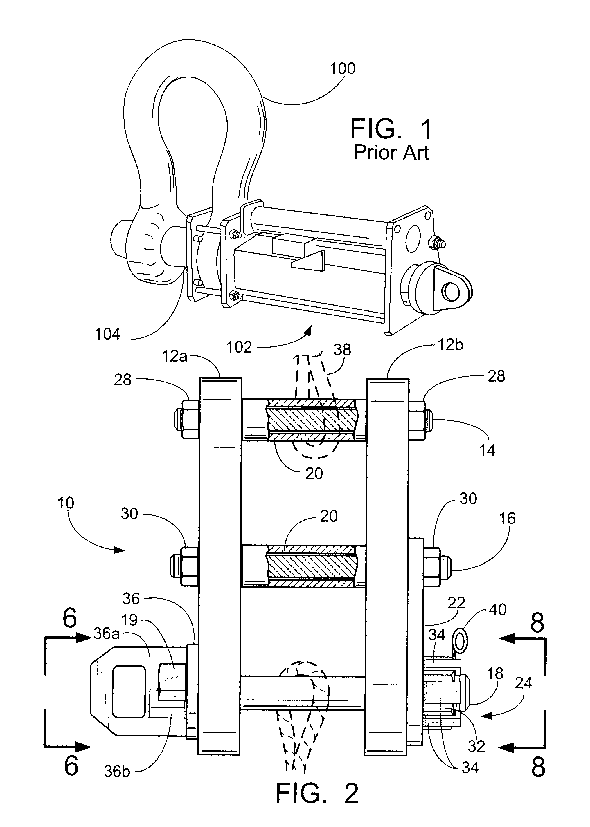
[0019]FIG. 1 illustrates a prior art hydraulic release mechanism. A shackle 100 has a hydraulic cylinder 102 attached thereto. The ram 104 of the hydraulic cylinder 102 extends through the bores in the shackle and acts as the release pin for supporting, lowering, and releasing a load.

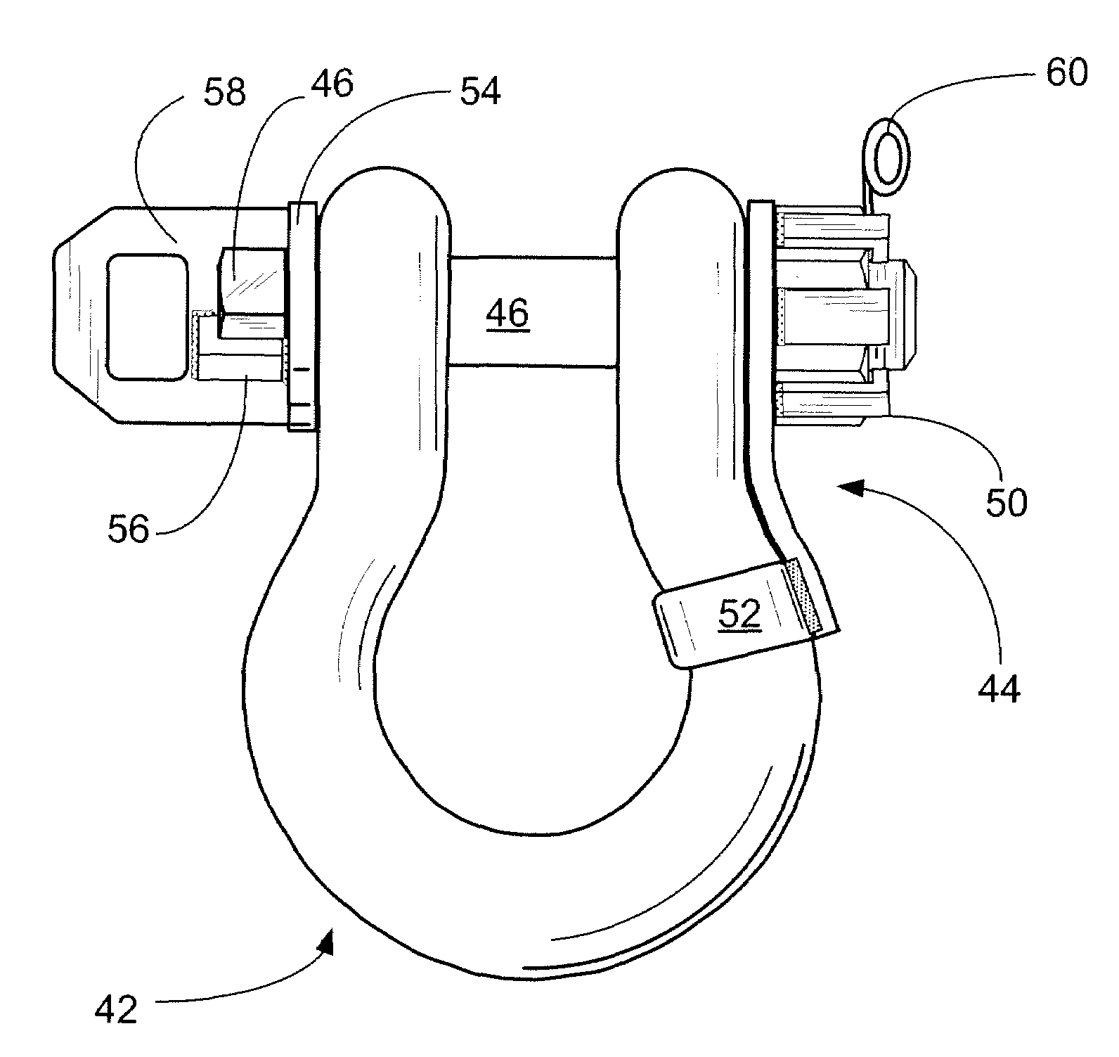
[0020]The invention is generally directed to a shackle arrangement that provides for the mechanical gripping, rotation, and removal of a shackle pin from a shackle arrangement, means for capturing the shackle nut to prevent loss, and means for preventing rotation of the shackle nut during rotation of the shackle pin. The invention may be practiced with the different embodiments illustrated in FIGS. 2-8 of a specially constructed arrangement or as illustrated in FIGS. 9-10 by the modification of a pre-existing shackle arrangement. Both embodiments are described below.

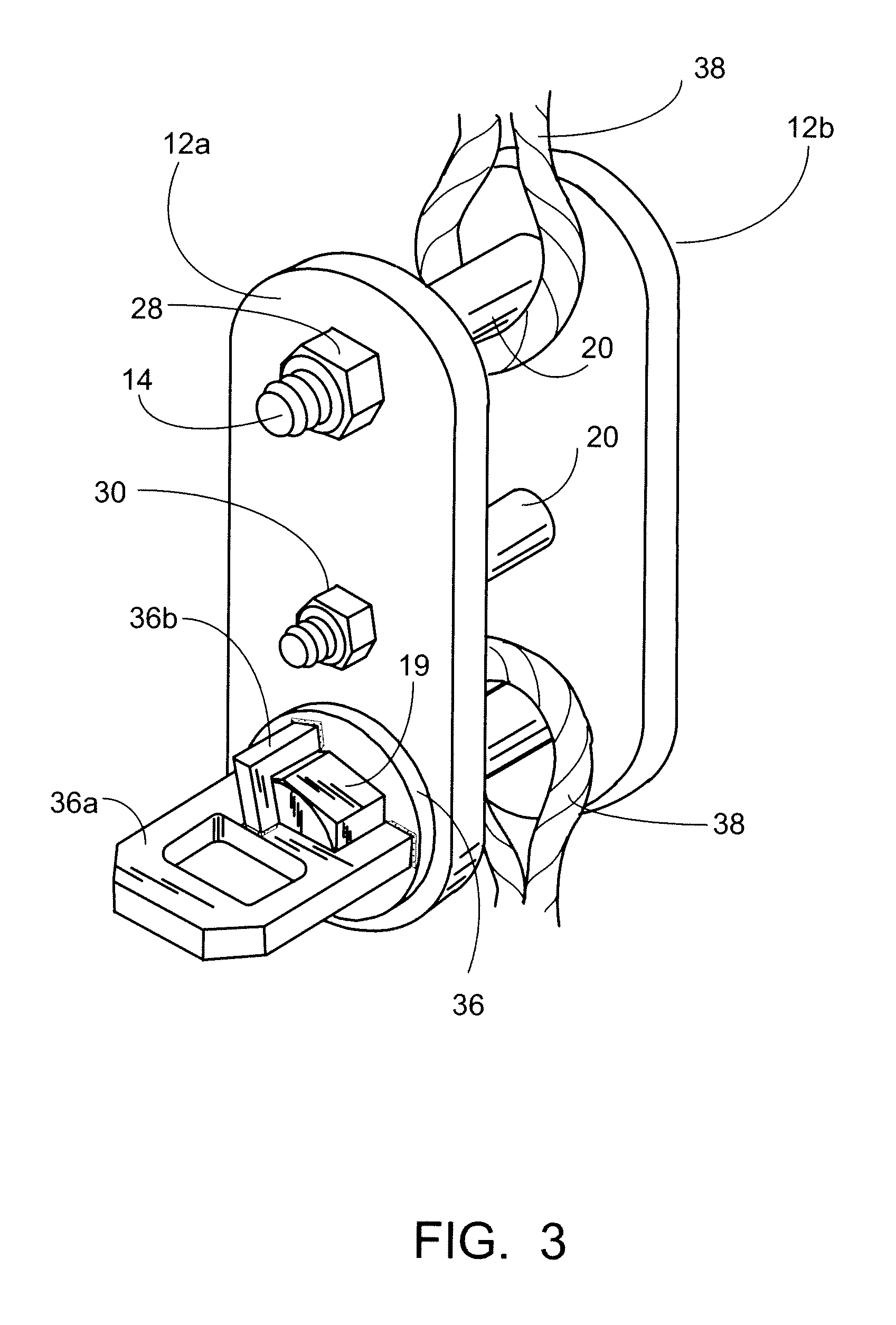
[0021]As seen in the embodiment of FIGS. 2-4, mechanically releasable shackle 10 is generally comprised of two main side plates 12a, b, bol...


PUM


Abstract

A mechanically releasable shackle pin arrangement that is readily operated by an ROV and is not affected by the hydrostatic pressures encountered at depth. A shackle body having two ends has a shackle pin received through bores at one end of the shackle body. A shackle nut threaded on the shackle pin secures the shackle pin in an installed position through the bores in the shackle body. An anti-rotation link plate is attached to the shackle body. The anti-rotation link plate extends to one end of the side plate. The shackle pin extends through bores at one end of the shackle body and the anti-rotation link plate and is secured in its installed position by a shackle nut threaded on the shackle pin. Means for preventing rotation of the shackle nut and loss of the shackle nut is provided on the anti-rotation link plate such that the shackle pin can be removed by a remotely operated tool on an ROV at depth to release a load without the need for hydraulics on the shackle assembly. The shackle pin is provided with a special plate arrangement designed to allow the shackle pin to be gripped and rotated by a remotely operated tool on an ROV.

Description

FIELD AND BACKGROUND OF INVENTION[0001]The invention is generally related to the use of shackles used to lift and lower equipment and more particularly to a means of releasing the equipment from the shackles.[0002]In the offshore oil and gas industry, it is routinely necessary to lower equipment to the sea floor or to specific levels of structures underwater. Because of the water depths involved, as deep as 5,000 feet or deeper, it is often unsafe and impractical to use divers. At these depths, use of an ROV (Remotely Operated Vehicle) is preferred for underwater operations.[0003]In the past it has been common to use a hydraulic shackle pin release mechanism that enabled shackles to be removed from equipment underwater without substantial outside assistance. The hydraulic release mechanism can be remotely activated by an ROV, thus allowing surface vessels to lower equipment and disengage the attached rigging without the support of divers.[0004]As seen in the prior art drawing of FIG...

Claims


Application Information

Patent Timeline
IPC IPC(8): B66C1/34F16G15/06
CPCF16G15/06Y10T403/598
Inventor PAYNE, JACK DARRYLLANDRY, TAIT JAMESGOLJENBOOM, JAMES L.ORDOYNE, RICHARD JOSEPHDUNBAR, TIMOTHY A.
Owner J RAY MCCDERMOTT SA
Why Eureka
Try Eureka