
Audio signal encoding apparatus and method

a technology of audio signal and encoding apparatus, which is applied in the field of audio signal encoding apparatus and method, can solve the problems of large computational complexity, large computational complexity, and large computational complexity, and achieve the reduction of computational complexity required for quantization processing, reducing computational complexity, and improving sound quality

Inactive Publication Date: 2009-11-03
CANON KK
View PDF13 Cites 15 Cited by
  • Summary
  • Abstract
  • Description
  • Claims
  • Application Information

AI Technical Summary

Benefits of technology

[0032]As processing that requires high computational complexity as well as the quantization processing, psychoacoustic analysis is known. When a reduction of the computational complexity has priority over encoding efficiency and, more particularly, when, for example, a reduction of consumption power has priority over sound quality in a relatively inexpensive portable video capturing device or the like, encoding can be done without any psychoacoustic analysis. At this time, in the quantization processing, scale factors are uniformly set to be the same value in all the decomposed frequency bands, thus removing the outer distortion control loop and reducing the computational complexity.
[0035]It is, therefore, an object of the present invention to reduce the computational complexity required for the quantization processing in audio signal encoding.
[0036]It is another object of the present invention to reduce the computational complexity required for quantization while minimizing deterioration of sound quality due to non-execution of psychoacoustic analysis in audio encoding configured not to execute any psychoacoustic analysis.Means of Solving the Problems

Problems solved by technology

Since there are 11 different Huffman code tables to be searched upon bit calculations, if the Huffman code tables are fully searched, the calculation amount of the bit calculations inevitably becomes large.
Furthermore, in the distortion control loop, the quantization errors are calculated after inverse quantization, and this processing also requires high computational complexity.
For this reason, a huge computational complexity is required until the double loops converge.

Method used


Image

  • Audio signal encoding apparatus and method
  • Audio signal encoding apparatus and method
  • Audio signal encoding apparatus and method

Examples


first embodiment

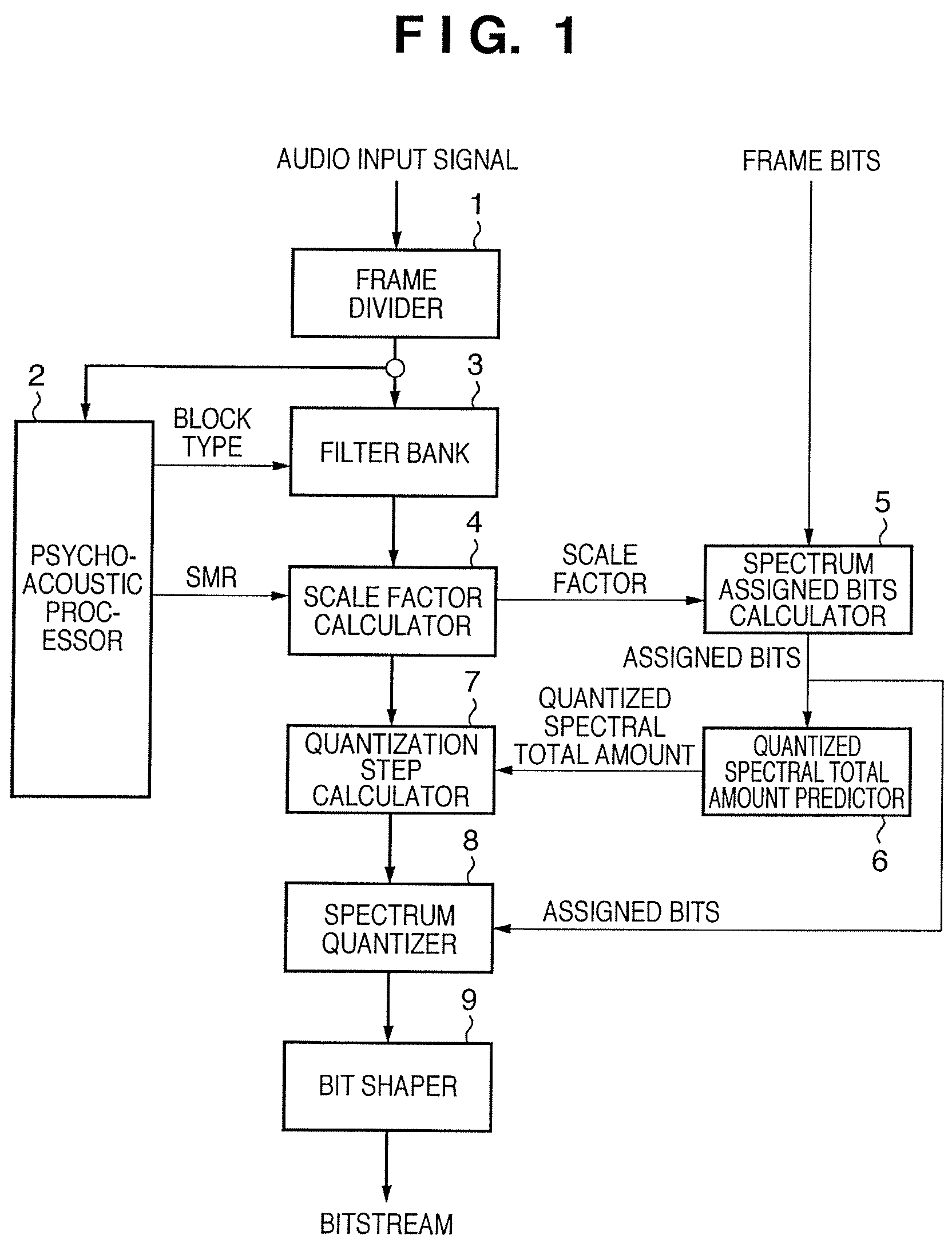
[0063]FIG. 1 is a block diagram showing an example of the arrangement of an audio signal encoding apparatus according to this embodiment. In FIG. 1, the bold lines indicate a data signal, and the thin lines indicate a control signal.

[0064]In the arrangement shown in FIG. 1, reference numeral 1 denotes a frame divider which divides an audio input signal into frames as processing units. The audio input signal divided into frames is sent to a psychoacoustic processor 2 and filter bank 3 (to be described below).

[0065]Reference numeral 2 denotes a psychoacoustic processor, which analyzes the audio input signal for respective frames, and makes masking calculations in decomposed frequency bands more elaborate than SFBs. As a result of the arithmetic operations, a block type is output to the filter bank 3, and a signal to mask ratio (SMR) for each SFB is output to a scale factor calculator 4.

[0066]Reference numeral 3 denotes a filter bank, which applies a window of the block type designated...

second embodiment

[0100]The present invention can also be practiced as a software program which runs on a general-purpose computer such as a personal computer (PC) or the like.

[0101]FIG. 5 is a block diagram showing an example of the arrangement of an audio signal encoding apparatus according to this embodiment.

[0102]In the arrangement shown in FIG. 5, reference numeral 100 denotes a CPU which makes arithmetic operations, logical decisions, and the like for audio signal encoding processing, and controls respective building components via a bus 102.

[0103]Reference numeral 101 denotes a memory which stores a basic I / O program in the arrangement example of this embodiment, program codes in execution, data required upon program processing, and the like.

[0104]Reference numeral 102 denotes a bus, which transfers an address signal that designates a building component to be controlled by the CPU 100, transfers a control signal of each building component to be controlled by the CPU 100, and performs data tran...

third embodiment

[0151]The technique of the present invention can be applied to even a case in which reserved bits reserved in the bit reservoir are distributed to respective frames as needed depending on the characteristics of an input signal upon encoding at a fixed bit rate. This embodiment will explain this case with reference to the drawings.

[0152]FIG. 10 is a block diagram showing an example of the arrangement of an audio signal encoding apparatus according to this embodiment. As in FIG. 1 according to the first embodiment, in FIG. 10, the bold lines indicate a data signal, and the thin lines indicate a control signal. Also, in FIG. 10, the same reference numerals denote the same building components having the same functions as in FIG. 1.

[0153]In the arrangement shown in FIG. 10, reference numeral 1 denotes a frame divider; 2, a psychoacoustic processor; 3, a filter bank; 4, a scale factor calculator; 7, a quantization step calculator; 8, a spectrum quantizer; and 9, a bit shaper.

[0154]Referen...


PUM


Abstract

An audio signal encoding apparatus includes a frame dividing unit (1), an auditory psychological arithmetic unit (2), a filter bank unit (3), a scale factor calculation unit (4) which weights the spectra in the respective frequency bands by an arithmetic result of the auditory psychological arithmetic unit (2), a quantization step determination unit (7) which determines a quantization step of the entire frame prior to spectrum quantization by subtracting an information size of all quantized spectra from an auditory information size of all the weighted spectra before quantization, and multiplying the difference by a coefficient obtained from a step width of a quantization coarseness, a spectrum quantization unit (8), and a bit shaping unit (9) which outputs a bitstream obtained by shaping quantized spectra. The quantization step determination unit predicts the information size of all the quantized spectra based on a bit size assigned to a frame to be encoded.

Description

[0001]This application is a continuation of copending international patent application number PCT / JP2005 / 021014 filed Nov. 16, 2005TECHNICAL FIELD[0002]The present invention relates to an audio signal encoding apparatus and method.BACKGROUND ART[0003]In recent years, high-sound quality, high-efficiency audio signal encoding techniques are popularly used in audio tracks of DVD-Video, portable audio players, music delivery, music storage in a home server of a home LAN, and the like, and have prevailed, gaining significant importance.[0004]Most of such audio signal encoding techniques execute a time-frequency transform by exploiting transform coding techniques. For example, MPEG-2 AAC, Dolby Digital (AC-3), and the like form a filter bank by orthogonal transform alone such as MDCT (Modified Discrete Cosine Transform) or the like. Also, MPEG-1 Audio Layer III (MP3) and ATRAC (an encoding scheme used in an MD (MiniDisc)) form a filter bank by using a cascade of a subband filter such as Q...

Claims


Application Information

Patent Timeline
Patent Type & Authority Patents(United States)
IPC IPC(8): G10L19/00G10L19/02G10L19/035G10L19/04
CPCG10L19/04G10L19/035G10L19/0208G10L19/02
Inventor FUNAKOSHI, MASANOBU
Owner CANON KK
Learn More