
Cellular network service over WLAN

a cellular network and wlan technology, applied in the field of wireless communication, can solve the problems of slow handover from wlan to cellular network, degraded qos provided by ancillary network connection, degradation, etc., and achieve the effect of constant transmission bandwidth, maximizing the number of calls carried, and minimizing the volume of data traffi

Inactive Publication Date: 2009-11-03
ZEHAVI EPHRAIM
View PDF13 Cites 92 Cited by
  • Summary
  • Abstract
  • Description
  • Claims
  • Application Information

AI Technical Summary

Benefits of technology

"The present invention provides a novel approach to integrating a cellular network with a WLAN, allowing for seamless handover and seamless handover between the two networks. This is achieved by using an information switching controller (ISC) that interfaces between the cellular network and the WLAN. The mobile station has dual interfaces for communicating with the cellular network and the WLAN, and the ISC opens a first connection to the cellular network and a second connection to the WLAN. While the first connection remains open, the second connection is opened to provide a better quality of service (QoS) for the call. The invention allows for seamless handover and provides a better user experience for calls that involve streaming media such as voice and video calls. The invention also allows for the integration of other types of ancillary networks, such as another cellular network or a packet network, and provides interoperability between the two networks."

Problems solved by technology

It may often occur during the course of the call that the QoS provided by the ancillary network connection degrades.
Assuming the ancillary network to be a WLAN, for example, such degradation may occur if the user of the mobile station moves out of the coverage area of the WLAN, or if other data traffic or interference increases abruptly.
By contrast, in loosely-coupled models of cellular / WLAN integration, handover from the WLAN to the cellular network is slow—typically lasting as long as ten seconds—since a new connection must be established between the mobile station and the cellular network before data communications can resume.
This lengthy handover may be tolerable in non-streaming packet data applications, but for voice and video calls it is clearly unacceptable.
Tightly-coupled models are capable of seamless handover, but require large investments in infrastructure and suffer from other practical problems, as noted in the Background.

Method used


Image

  • Cellular network service over WLAN
  • Cellular network service over WLAN
  • Cellular network service over WLAN

Examples


Embodiment Construction

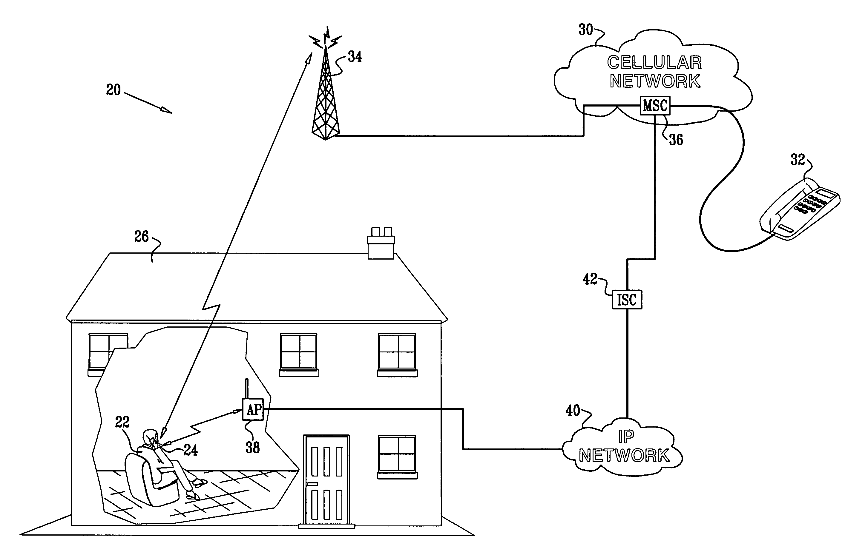
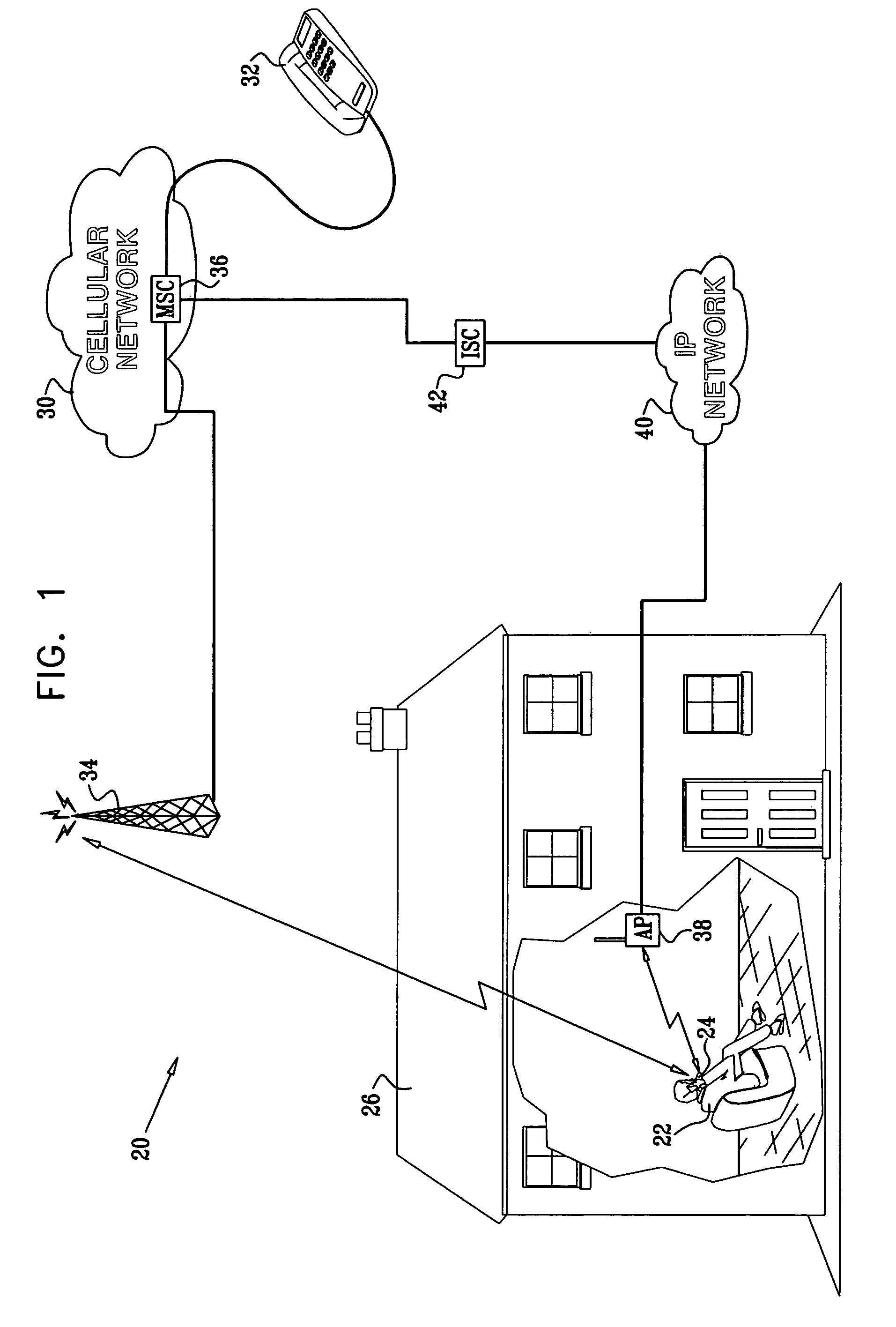
[0052]FIG. 1 is a schematic, pictorial illustration of a hybrid communication system 20, in accordance with an embodiment of the present invention. In the scenario shown in FIG. 1, a telephone user 22 in a building 26 places (or receives) a call on a mobile station 24 via a cellular telephone network 30 to (or from) another subscriber telephone 32. The call is established via a radio connection between telephone 24 and a cellular base station 34. Signals are transmitted between the base station and a switch 36 in network 30, and from the switch to telephone 32.

[0053]In this embodiment, network 30 is assumed to be a second-generation cellular voice network, such as a GSM or CDMA network, and switch 36 is identified for convenience as a mobile switching center (MSC). Alternatively, network 30 may comprise a 3G or other cellular packet network, such as a CDMA2000 or UMTS network, in which case base station 34 could comprise a radio network controller (RNC), while switch 36 comprises a ...


PUM


Abstract

A method for communication includes initiating a call between a mobile station in a cellular communication network and a subscriber unit that is accessible via the cellular communication network. A first connection to serve the call is opened between a base station in the cellular communication network and the mobile station. A second connection to serve the call is opened between the mobile station and an access point in a wireless local area network (WLAN). While the first connection is open, data traffic is conveyed between the mobile station and the subscriber unit via the second connection.

Description

FIELD OF THE INVENTION[0001]The present invention relates generally to wireless communications, and specifically to integration of a wireless local area network (WLAN) into a cellular telephone network.BACKGROUND OF THE INVENTION[0002]There has recently been growing interest in the possibility of integrating WLAN and cellular network services. Buddhikot et al. provide a useful overview of proposed approaches to WLAN / cellular integration for wireless data services in “Integration of 802.11 and Third-Generation Wireless Data Networks,”Proceedings of IEEE Infocom 2003 (San Francisco, April, 2003), which is incorporated herein by reference.[0003]WLANs operating in accordance with the IEEE 802.11 standards operate in the unlicensed ISM bands and support data rates between 1 Mbps and 54 Mbps, at low capital cost. WLAN access points, however, are generally limited in range, covering areas no bigger than a few thousand square meters. They are most commonly deployed indoors, in business faci...

Claims


Application Information

Patent Timeline
Patent Type & Authority Patents(United States)
IPC IPC(8): H04L12/66H04W36/14H04W84/12H04W88/06
CPCH04L12/5692H04W36/14H04W88/06H04W84/12H04W36/1446
Inventor ZEHAVI, EPHRAIMHERZLICH, DORON
Owner ZEHAVI EPHRAIM
Learn More