
Surface-potential distribution measuring apparatus, image carrier, and image forming apparatus

a measuring apparatus and surface-potential technology, applied in the field of surface-potential distribution measuring apparatus, image carrier, image forming apparatus, can solve the problems of inability to hold the charge, time-consuming preparation of observation, and inability to accurately observe the sample of conventional technology

Active Publication Date: 2009-11-03
RICOH KK
View PDF33 Cites 9 Cited by
  • Summary
  • Abstract
  • Description
  • Claims
  • Application Information

AI Technical Summary

Problems solved by technology

The conventional technology requires time to prepare the observation.
However, when the normal photoconductor is used as a sample, this sample cannot hold the charge during a long time, and, for example, the electrostatic latent image disappears at the observation preparation stage, making it impossible to accurately observe the sample.
However, because a sensor probe needs to be set to a position with a distance from the sample in principle, space resolution is only a few millimeters or above, and the vibrating reed electrometer finds it difficult to measure a potential in a region of 1 millimeter or below.
According to this conventional technology, a sample to be observed is limited to a large-scale integration (LSI) chip and a sample that can store and hold the electrostatic latent image.
However, because a resistance value of the photoconductor is not infinitely large, the photoconductor cannot hold the charge during a long time.
However, with these conventional technologies, it has been difficult to measure a surface electrification and a surface potential in high resolution of a micron order, and there has been room for improvement in evaluating the electrostatic latent image formed on the photoconductor of the image forming apparatus.

Method used


Image

  • Surface-potential distribution measuring apparatus, image carrier, and image forming apparatus
  • Surface-potential distribution measuring apparatus, image carrier, and image forming apparatus
  • Surface-potential distribution measuring apparatus, image carrier, and image forming apparatus

Examples


first embodiment

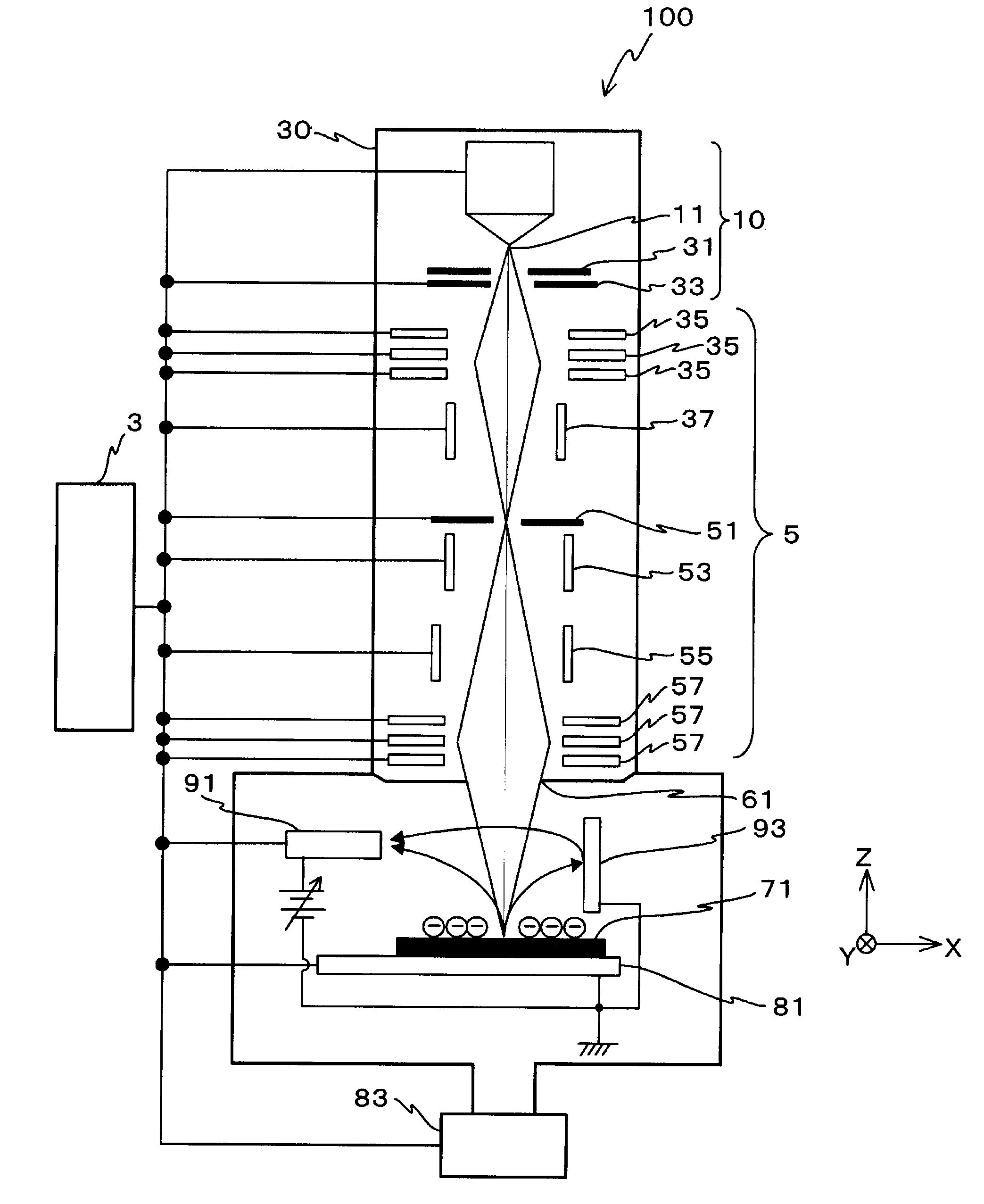
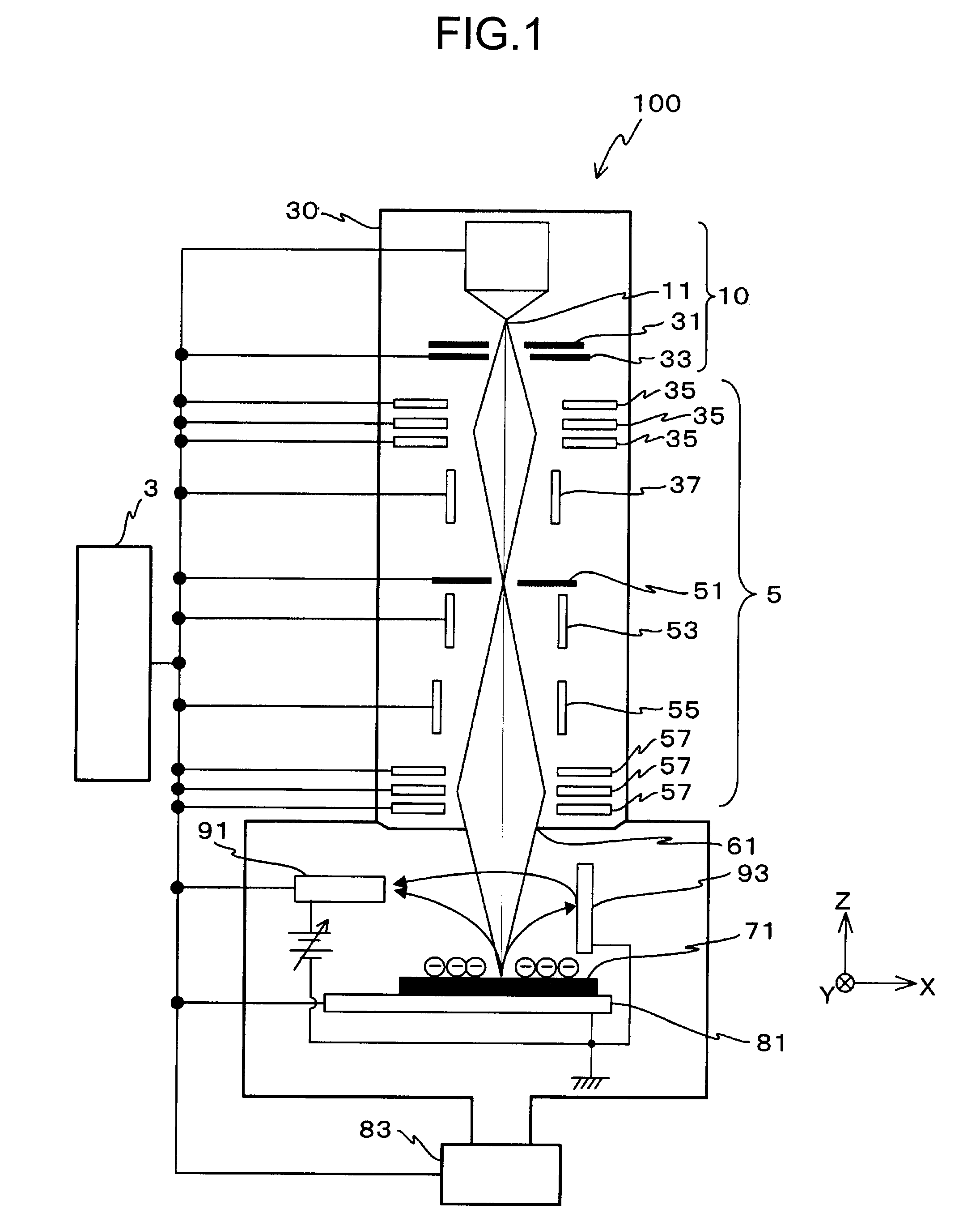
[0059]the present invention is explained below with reference to FIGS. 1 to 9C. FIG. 1 is a schematic diagram of a surface-potential distribution measuring apparatus 100 according to the first embodiment.

[0060]The surface-potential distribution measuring apparatus 100 includes an electron gun 10, a casing 30, a condenser lens (electrostatic lens) 35, a beam-blanking electrode 37, an aperture 51, a stigmator 53, a scanning lens (deflection electrode) 55, an objective lens 57, a sample table 81, a detector 91, an electron-emission panel 93, a control system 3, an exhaust system 83, and a driving power source (not shown). In the following description, an optical axis direction of each lens is explained as a Z-axis direction, and two directions mutually orthogonal within a plane perpendicular to the Z-axis direction are explained as an X-axis direction and a Y-axis direction.

[0061]The electron gun 10 emits an electron beam. The electron gun 10 includes an emitter 11, an extraction elect...

second embodiment

[0155]the present invention is explained next. The surface-potential measuring method and the surface-potential measuring method can measure, in potential resolution of a few volts, a few hundred to a few thousand surface potentials and charge, even in a small region of 1 millimeter or smaller of an electrostatic latent image on a photoconductor, which it has been difficult to achieve according to the conventional technique. The image carrier (photoconductor) has high performance, evaluated by the above method and the above device. The image forming apparatus includes this high-performance image carrier.

[0156]The surface charge explained herein is scattered in space within the sample, as is widely known. Therefore, it is assumed that the surface charge is distributed in a larger area in the in-plane direction than in the thickness direction. The electric charge includes not only electrons but also ions. A conductive part can be present on the surface, a voltage can be applied to the...


PUM


Abstract

A surface-potential distribution measuring apparatus includes an electron gun, an electron-beam optical system, an electron-emission panel, a detector, and a control system. The electron-beam optical system is located between the electron gun and a sample, and focuses a beam of electrons emitted from the electron gun to the surface of the sample. The electron-emission panel is located near the sample to be collided with at least part of the electrons via the sample, and emits secondary electrons corresponding to the number of collided electrons. The detector detects at least part of the secondary electrons. The control system obtains potential distribution on the surface of the sample based on a detection result obtained by the detector.

Description

CROSS-REFERENCE TO RELATED APPLICATIONS[0001]The present application claims priority to and incorporates by reference the entire contents of Japanese priority document, 2006-233005 filed in Japan on Aug. 30, 2006, and Japanese priority document, 2006-253048 filed in Japan on Sep. 19, 2006.BACKGROUND OF THE INVENTION[0002]1. Field of the Invention[0003]The present invention relates to a surface-potential distribution measuring apparatus, an image carrier, and an image forming apparatus.[0004]2. Description of the Related Art[0005]Electrophotographic image forming apparatuses such as a laser printer and a digital copier focus light beams from a light source modulated according to image information on a photoconductor via a scanning optical system, and scans the light beams on the photoconductor in a predetermined direction (main scanning direction), thereby forming an electrostatic latent image on the photoconductor. The image forming apparatus makes toner adhere to the electrostatic ...

Claims


Application Information

Patent Timeline
Patent Type & Authority Patents(United States)
IPC IPC(8): G01R31/305
CPCG03G15/5037H01J37/244H01J37/268G03G2215/00033G03G2215/00054H01J2237/2594H01J2237/0047H01J2237/0048H01J2237/2444H01J2237/24564G01R31/305
Inventor SUHARA, HIROYUKI
Owner RICOH KK
Learn More