Method to control BAW resonator top electrode edge during patterning

a top electrode edge and patterning technology, applied in the field of piezoelectric resonators, can solve problems such as undercutting voids at the device periphery, negative impact on the performance of piezoelectric resonators, and voids that cannot be occupied by the top electrode edge of the baw resonator, and achieve the effect of superior piezoelectric resonator architecture and good control

Active Publication Date: 2009-11-03
QORVO US INC
View PDF19 Cites 18 Cited by
  • Summary
  • Abstract
  • Description
  • Claims
  • Application Information

AI Technical Summary

Benefits of technology

[0009]Embodiments of a piezoelectric resonator include a multi-layer top electrode. The multi-layer top electrode includes at least a top metal layer and a bottom metal layer. A top metal layer edge is recessed compared to a bottom metal layer edge allowing conformal deposition of a passivation layer. The passivation layer covers and protects the underlying layers from subsequent etching, thereby preventing etch undercut of the top electrode. Preventing etch undercut provides a superior piezoelectric resonator architecture because of good control of the active area in-plane dimensions. In some embodiments, the multi-layer top electrode is configured as a bi-layer. In other embodiments, an extra layer is configured between the top metal layer and the bottom metal layer, for example a shunt load layer.
[0011]The multi-layer top electrode construction is desirable in BAW resonator design that require stringent acoustic, electrical, and process integration requirements. By using two distinct materials for the multi-layer configuration, it is possible to benefit from the unique properties of each material.

Problems solved by technology

In either case, undercutting of the top metal layer 54 negatively impacts the performance of the piezoelectric resonator.
During fabrication of conventional piezoelectric resonators, such as the process illustrated in FIGS. 2-5, problems arise during etching of the bi-layer top electrode and during etching of the metallization layer that contacts the top electrode bi-layer stack.
The difficulty is finding etches that do not preferentially attack the bottom metal layer 52 causing undercut voiding at the device periphery.

Method used


Image

  • Method to control BAW resonator top electrode edge during patterning
  • Method to control BAW resonator top electrode edge during patterning
  • Method to control BAW resonator top electrode edge during patterning

Examples


Embodiment Construction

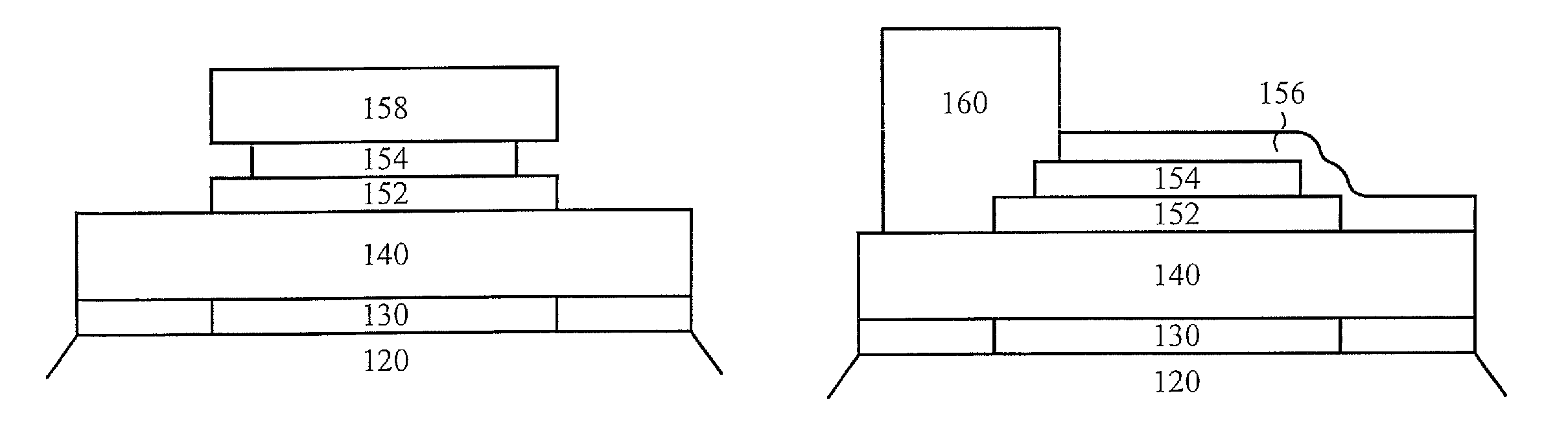
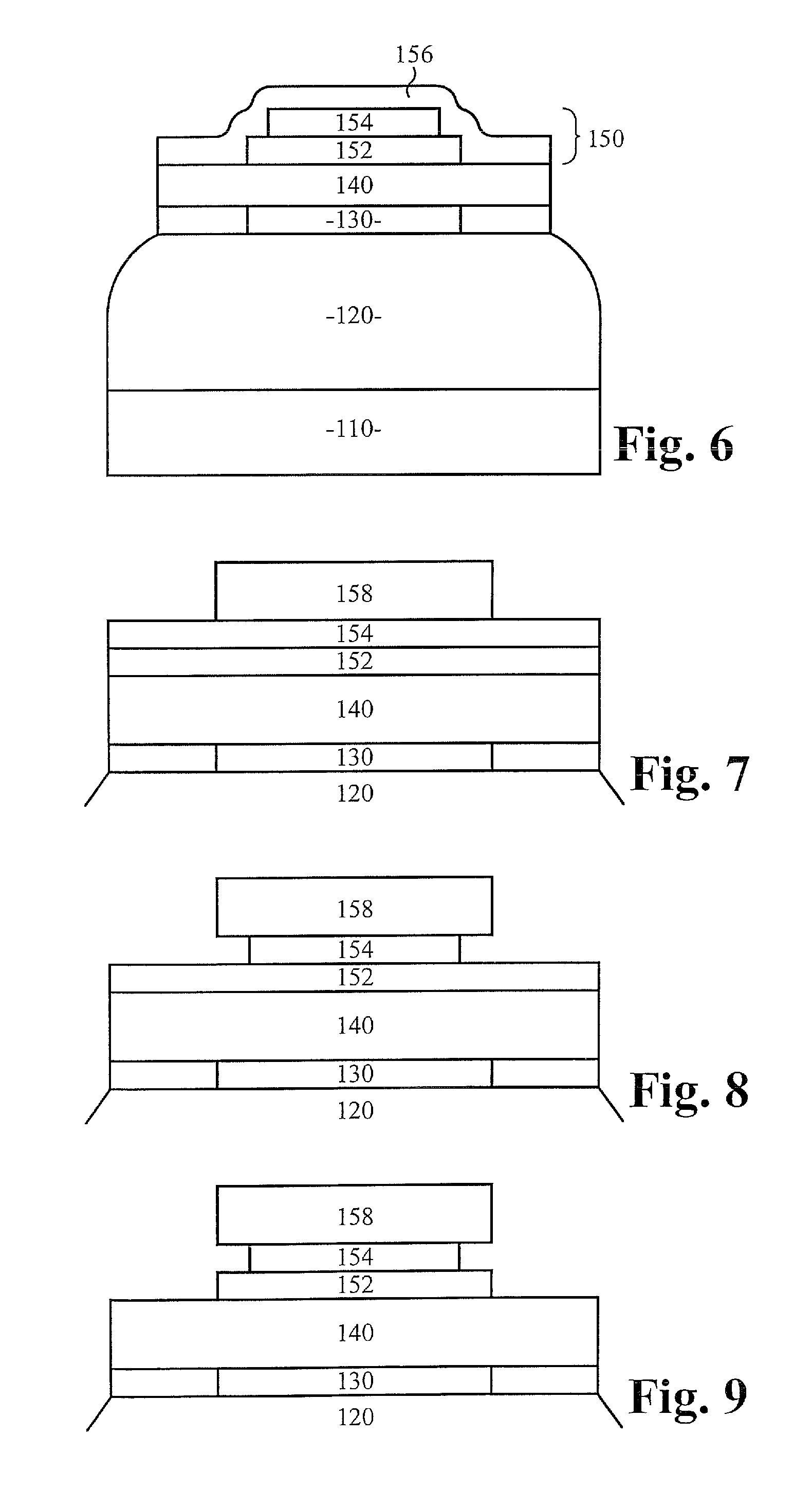
[0024]FIG. 6 illustrates a cross-section side view of a first embodiment of the piezoelectric resonator. The piezoelectric resonator includes an acoustic mirror or acoustic reflector 120 formed on a substrate 110 preferably by a deposition process. A bottom electrode 130 is formed on the acoustic reflector 120 preferably by a deposition process. A piezoelectric layer 140 is formed on the bottom electrode 130 preferably by a deposition process. A top electrode 150 is formed on the piezoelectric layer 140 preferably by a deposition process. In this first embodiment, the top electrode 150 is configured as a bi-layer electrode, including a top metal layer 154 formed on a bottom metal layer 152 preferably by a deposition process. The top metal layer 154 is formed relative to the bottom metal layer 152 such that a passivation layer 156 completely covers any exposed portion of both the top metal layer 154 and the bottom metal layer 152. In some embodiments, the outer edges of the top metal...


PUM

PropertyMeasurementUnit
resonance frequenciesaaaaaaaaaa
piezoelectricaaaaaaaaaa
perimeteraaaaaaaaaa

Abstract

A piezoelectric resonator include a multi-layer top electrode. The multi-layer top electrode includes at least a top metal layer and a bottom metal layer. A top metal layer edge is recessed compared to a bottom metal layer edge allowing conformal deposition of a passivation layer. The passivation layer covers and protects the underlying layers from subsequent etching, thereby preventing etch undercut of the top electrode. In some embodiments, the multi-layer top electrode is configured as a bi-layer. In other embodiments, an extra layer is configured between the top metal layer and the bottom metal layer, for example a shunt load layer.

Description

FIELD OF THE INVENTION[0001]The present invention relates to the field of piezoelectric resonators. More particularly, the present invention relates to the field of a bulk acoustic wave (BAW) resonator and a method of controlling a top electrode edge of a BAW resonator during patterning.BACKGROUND OF THE INVENTION[0002]Piezoelectric resonators are primarily used in RF filters and oscillators. RF filters are increasingly being used in mobile communications devices. These resonators are commonly referred to as bulk acoustic wave (BAW) resonators. Other acronyms for the same or similar devices include FBAR (thin-film bulk acoustic resonators), SMR (solidly mounted resonators), TFR (thin film resonators), or SCR (stacked crystal resonators). The resonators are interconnected, typically at the upper metal level, to build RF filters.[0003]It is known that a bulk acoustic wave (BAW) resonator in general comprises a piezoelectric layer sandwiched between two electronically conductive layers...

Claims


Application Information

Patent Timeline
Patent Type & Authority Patents(United States)
IPC IPC(8): H01L41/06
CPCH03H9/589H03H9/131Y10T29/42Y10T29/49156
Inventor BOUCHE, GUILLAUMEWALL, RALPH N.
Owner QORVO US INC
Why Eureka
Try Eureka