Molding metal mold and method for producing a molded item

a metal mold and mold technology, applied in the field of molding metal molds, can solve the problems of molded item thickness and burrs, and the shape of molded items is not accurate, and achieves the effect of accurate positioning and high-quality shap

Inactive Publication Date: 2009-11-03
FUJIFILM HLDG CORP +1
View PDF14 Cites 0 Cited by
  • Summary
  • Abstract
  • Description
  • Claims
  • Application Information

AI Technical Summary

Benefits of technology

[0014]Thus, according to the present invention, the first convex taper and the first concave taper for positioning the first and second metal molds are fitted to abut not only by the respective taper surfaces but also by the parting surfaces around the cavity by means of the clamping force. Therefore, not only two-dimensional positions along the surface perpendicular to the axis of the first convex taper and the first concave taper, but positions in the axial direction are also accurately determined. As a result, the cavity has an accurate shape after the molds are clamped, allowing production of a molded item with a highly accurate shape.
[0019]The first metal mold is formed by the first insert and the first body member separated from each other, and the first insert is located inside and coaxially with the first convex taper. Thus, in the first body member, the first convex taper and a hole to insert the first insert can be processed in one chuck processing, and can have an accurate positional relationship to each other. Accordingly, the cavity can have a shape as designed, thus allowing it to mold an item with a high precision.
[0024]The second metal mold is formed by the second insert and the second body member separated from each other, and the second insert is located inside and coaxially with the second concave taper. Thus, in the second body member, the second concave taper and a hole to insert the second insert can be processed in one chuck processing, and can have an accurate positional relationship to each other. Accordingly, the cavity can have a shape as designed, thus allowing it to mold an item with a high precision.
[0030]According to the present invention, the first and second metal molds are accurately positioned, so that it becomes possible to produce a molded item having a highly accurate shape.

Problems solved by technology

This clearance causes a disparity between the cavity surfaces of one and the other molds, resulting in an error in the shape of the molded items.
However, because the convex and concave tapers themselves have errors in dimension and shape, in order to make the taper surfaces to surely abut, there needs to be a clearance between the top surface of the convex taper (a flat surface on the top of the taper) and the bottom surface of the concave taper.
However, the clearance causes an error in thickness and burrs to the molded items.
However, the clearance led to a further problem of causing a positioning error.

Method used


Image

  • Molding metal mold and method for producing a molded item
  • Molding metal mold and method for producing a molded item
  • Molding metal mold and method for producing a molded item

Examples


first embodiment

[0038]Referring to the drawings, an embodiment of the present invention will be described in detail.

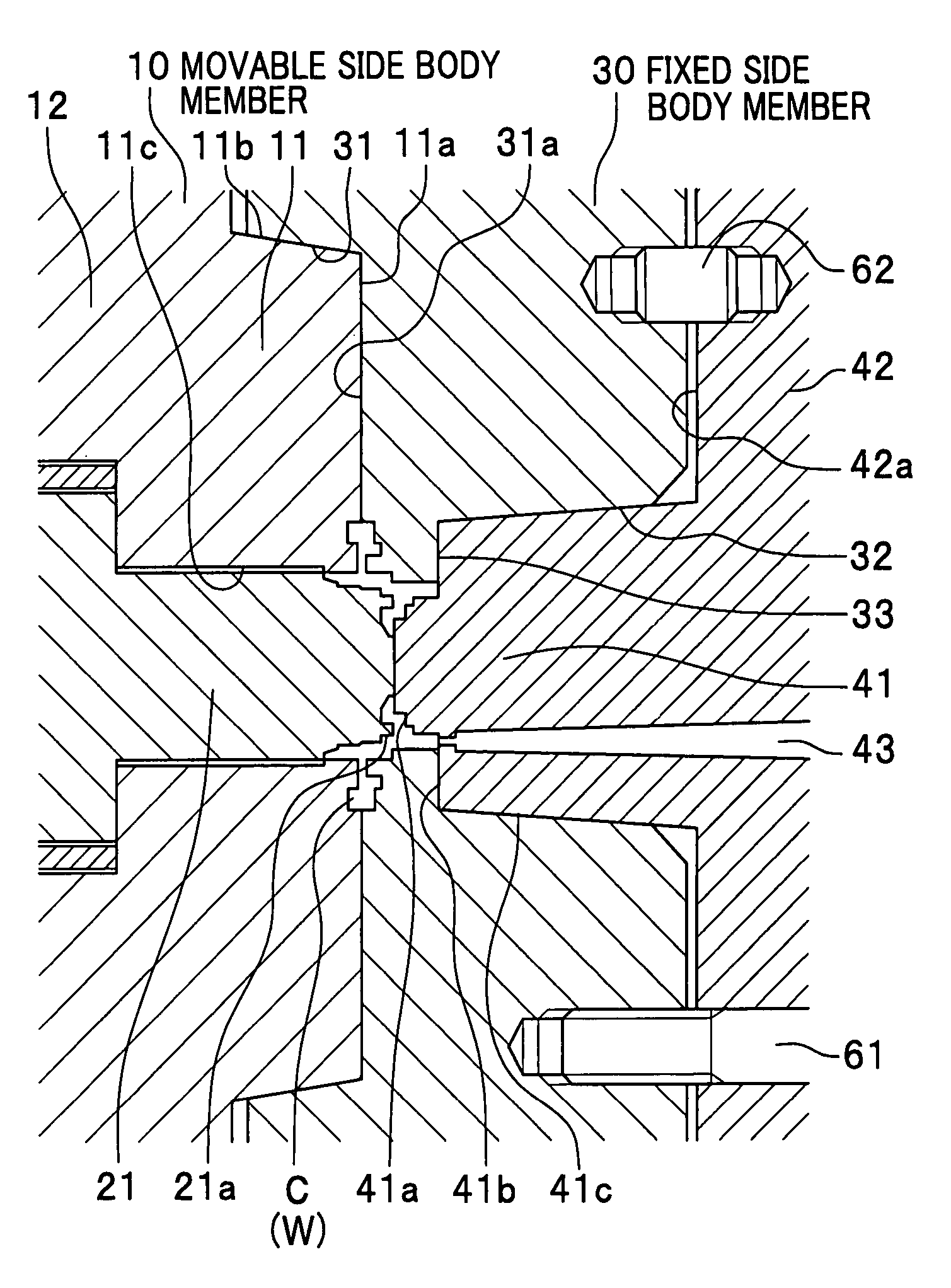
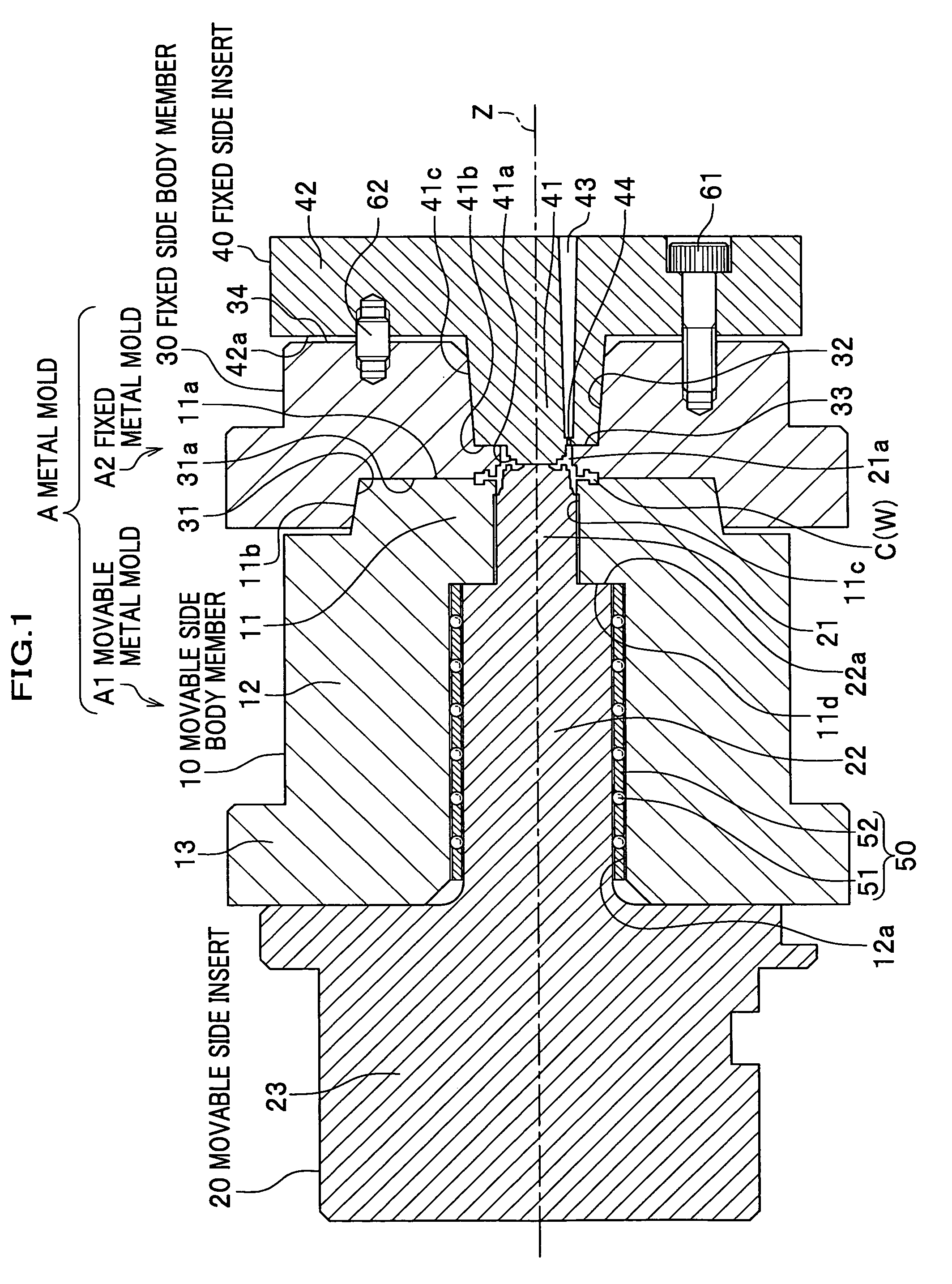
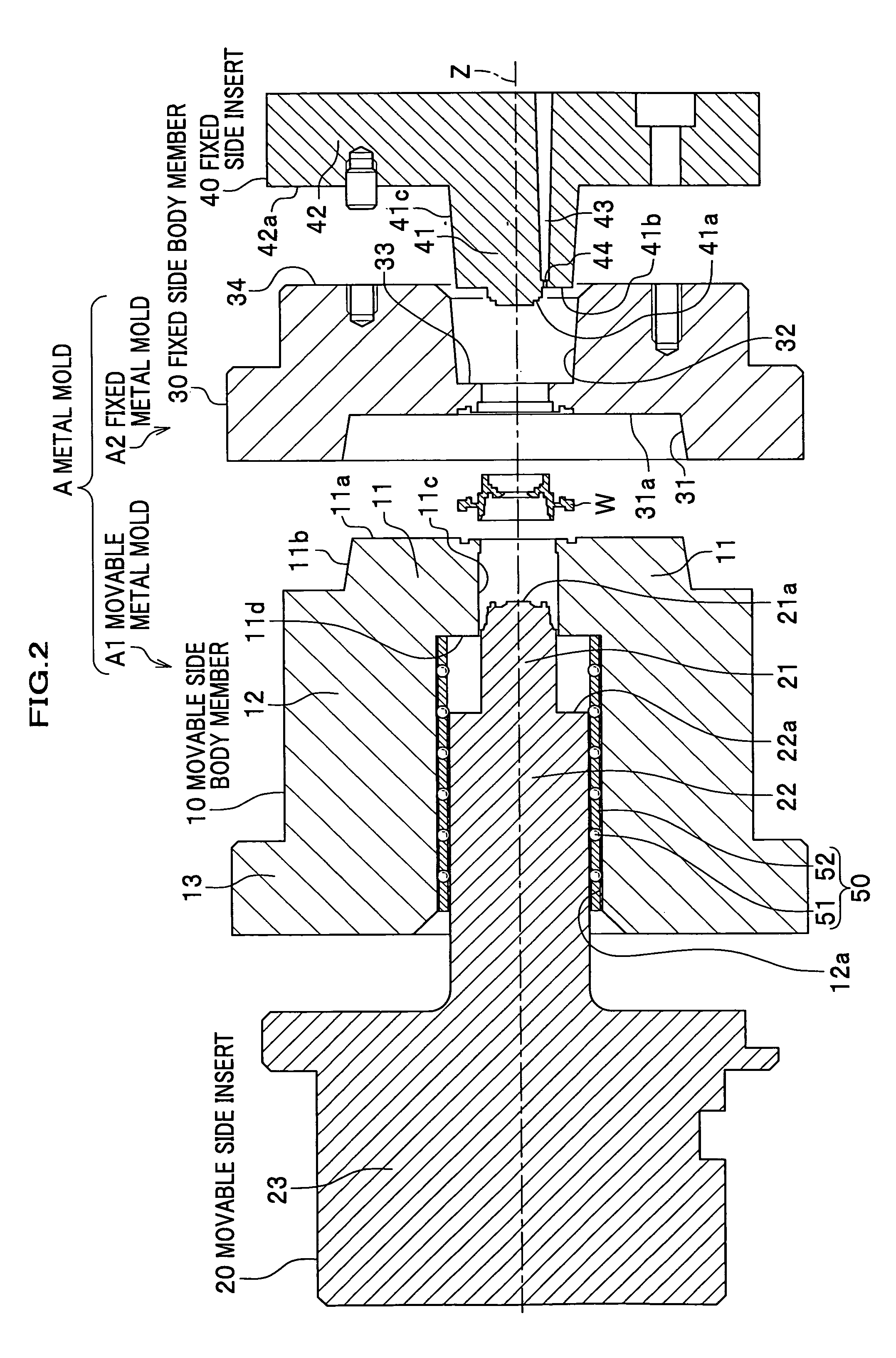
[0039]As shown in FIGS. 1 and 2, a molding metal mold A according to a first embodiment comprises a movable metal mold A1 as a first mold, and a fixed metal mold A2 as a second metal mold. The molding metal mold A is a mold for injection molding a tubular molded item W, for example, but is not limited thereto. The molding metal mold A of the invention can be preferably used particularly for producing molded items requiring high precision of shape wherein the mutual positional relationship between the movable metal mold A1 and the fixed metal mold A2 is considered especially important, such as an optical lens and an optical part such as a mirror frame for supporting the optical lens.

[0040]The movable metal mold A1 comprises a movable-side body member 10 as a first body member and a movable-side insert 20 as a first insert. The fixed metal mold A2 comprises a fixed-side body member 30 a...

second embodiment

[0064]Next, as a modification of the first embodiment, a second embodiment of the present invention will be discussed with reference to FIG. 4. FIG. 4 is a sectional view of a molding metal mold according to the second embodiment. The same portions as the first embodiment are denoted with the same symbols and descriptions thereof will be omitted.

[0065]As shown in FIG. 4, the molding metal mold B according to the second embodiment comprises a movable metal mold B1 and a fixed metal mold B2.

[0066]The movable metal mold B1 comprises a movable-side body member 10′ and a movable-side insert 70. In the molding metal mold A of the first embodiment, the movable-side body member 10 and the movable-side insert 20 are assembled in a mutually slidable (movable) manner while being relatively positioned by means of the linear bearing 50. In contrast, in the movable metal mold B1, mutual positioning between the movable-side body member 10′ and the movable-side insert 70 is carried out by means of ...


PUM

PropertyMeasurementUnit
center of gravityaaaaaaaaaa
fastening forceaaaaaaaaaa
gravityaaaaaaaaaa

Abstract

The present invention aims to allow production of a molded item having a highly precise shape. A molding metal mold is provided having a movable metal mold (first metal mold) and a fixed metal mold (second metal mold) defining a cavity therebetween in which a molded item is produced. The movable metal mold has a first convex taper tapering toward the fixed metal mold. The fixed metal mold has a first concave taper fittable with the first convex taper. The first convex taper and the first concave taper are arranged so that, when fitted to each other, respective taper surface abut to each other first, and then a clamping force of the movable metal mold and the fixed metal mold causes an abutting between an end surface and a bottom surface which are respective parting surfaces of the movable metal mold and the fixed metal mold around the cavity. The molding metal mold is used to produce a molded item by means of injection molding, for example.

Description

BACKGROUND OF THE INVENTION[0001]1. Field of the Invention[0002]The present invention relates to a molding metal mold, and more particularly, to a molding metal mold capable of improving the precision of the shape of the molded item.[0003]2. Description of the Related Art[0004]In general, in production of molded items having the same shape, methods are used such as pouring into a molding metal mold a material such as melted resin, and pressing a material in the molding metal mold. The molding metal mold is provided inside with a cavity having concavities and convexities reversed to those of the molded items to reflect the shape thereof. To pour the material into the cavity, the molding metal mold is separated into two or more portions at a parting surface passing through the cavity.[0005]Although the separate metal molds each have a positioning structure for positioning with a counterpart mold, when the positioning is conducted simply by fitting a pin into a hole, it is necessary to...

Claims


Application Information

Patent Timeline
Patent Type & Authority Patents(United States)
IPC IPC(8): B29C45/26B29C43/36
CPCB22D17/22B29C45/2606B29C33/303
Inventor WATANABE, SEIICHISHIGESADA, KEIJISAEKI, TATSUHIKOMISONOO, KAZUTOSHI
Owner FUJIFILM HLDG CORP
Why Eureka
Try Eureka