Seat structure, particularly for bicycle, having a customizable shock absorbing element between the shell

a seat structure and bicycle technology, applied in the field of seat structures, can solve the problems of elastomeric elements sliding, improper and unnatural positions, and almost totally inability to adjust the resilience of elastic members, and achieve the effect of uniform shock absorption all over the structur

Active Publication Date: 2009-11-03
SELLE ROYAL SPA
View PDF9 Cites 2 Cited by
  • Summary
  • Abstract
  • Description
  • Claims
  • Application Information

AI Technical Summary

Benefits of technology

[0012]The object of this invention is to overcome the above drawbacks, by providing a support structure that is highly efficient and relatively cost-effective.
[0013]A primary object is to provide a seat structure in which the shock and oscillation absorption properties may be adjusted, and a high user comfort is assured.
[0014]Another object is to provide a seat structure that is comfort even after many hours of use.

Problems solved by technology

An apparent limitation of such solutions is that the user is almost totally unable to adjust the resilience of elastic members as desired, thereby customizing the shock absorbing properties of the whole structure.
This prior art solution has the apparent drawback that the elastomeric elements are placed almost in direct contact with the ischial region of the user, thereby causing discomfort.
During normal use of the saddle, the user tends to move, thereby causing the elastomeric elements to slide relative to each other, and take improper and unnatural positions.
Unfortunately, the introduction of the insert is very difficult, thus dramatically affecting the efficiency of the shock absorbing member and the integrity of the whole seat structure.

Method used


Image

  • Seat structure, particularly for bicycle, having a customizable shock absorbing element between the shell
  • Seat structure, particularly for bicycle, having a customizable shock absorbing element between the shell
  • Seat structure, particularly for bicycle, having a customizable shock absorbing element between the shell

Examples


Embodiment Construction

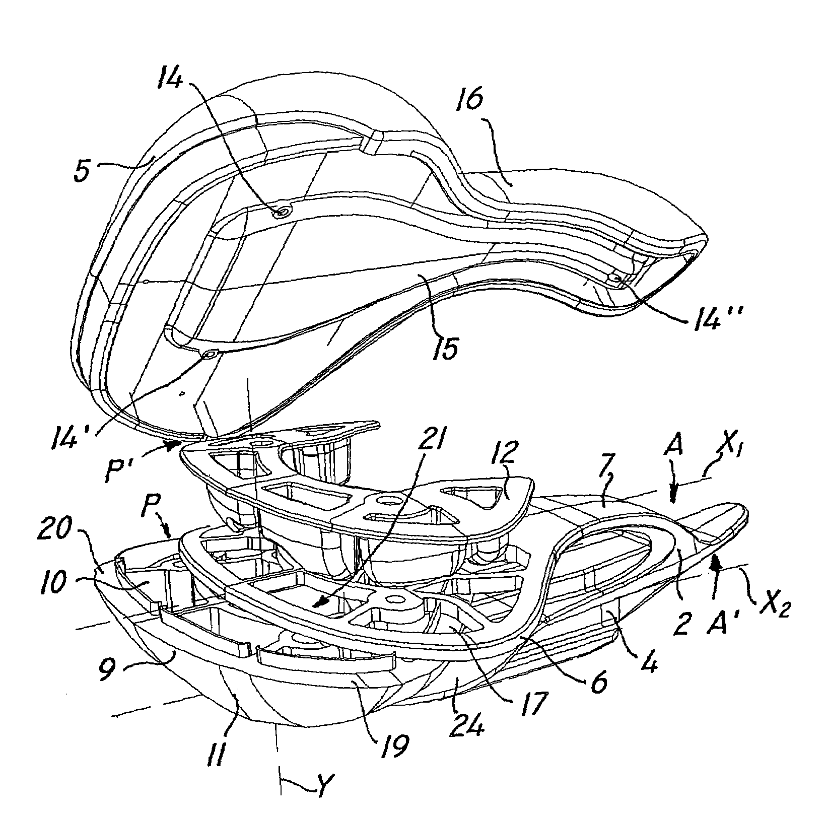
[0041]The seat structure of the invention is designed to support a seated user, and may have the form, for example, of a car seat, a chair or a bicycle saddle, as shown in the annexed figures.

[0042]As shown in FIGS. 1 and 2, the structure of the invention, overall designated with numeral 1, comprises, in a typical embodiment, a shell 2, which is composed of an upper support element 3 and an underlying connection member 4. The element 4 has the purpose of providing the connection with a movable or stationary frame T.

[0043]In accordance with a typical embodiment, an upper cover 5 is further provided, which is joined to the support element 3 and is designed to come in contact with the seated user.

[0044]The upper element 3 has in turn a downwardly facing bottom surface 6 and a top surface 7 for supporting the user's weight.

[0045]According to a preferred, non exclusive embodiment of the invention, the support element 3 and the connection member 4 are connected at one of their free ends, ...


PUM


Abstract

The present invention finds application in the field of sport and leisure accessories, and particularly relates to a seat structure having controlled and customizable elasticity, particularly for vehicles. The structure, which is designed to be connected to a movable or stationary frame, includes a support element having a bottom surface and a top surface, which is designed to support at least partly a user, a connection member to be associated to the support element for anchorage thereof to the movable or stationary frame, and at least one shock absorbing element, which is designed to absorb shocks and vibrations transmitted from the frame to the support element. The shock absorbing element includes an elastic member, which has a first elasticity modulus, and which is provided between the bottom surface of the support element and the connection member. Moreover, the elastic member has at least one seat for a corresponding insert, which has a second elasticity modulus, and which may be added by a user to control and selectively adjust the overall elasticity of the shock absorbing element.

Description

FIELD OF THE INVENTION[0001]The present invention finds application in the field of sport and leisure accessories, and particularly relates to a seat structure having controlled and customizable elasticity.BACKGROUND OF THE INVENTION[0002]Seating structures, such as bicycle saddles or car seats, are known to be designed to meet structural strength and compactness needs, in addition to user comfort and convenience requirements.[0003]In view of the above, a variety of solutions have been proposed to add comfort to such structures. For example, the seats have pads of resilient materials, such as sponge, foam, polyurethane foam or gel. Furthermore, they may have lower spring members or the like, to oppose the user's weight and to absorb any shock or abrupt oscillation.[0004]An apparent limitation of such solutions is that the user is almost totally unable to adjust the resilience of elastic members as desired, thereby customizing the shock absorbing properties of the whole structure.[00...

Claims


Application Information

Patent Timeline
Patent Type & Authority Patents(United States)
IPC IPC(8): B62J1/00
CPCB62J1/02
Inventor SEGATO, STEFANO
Owner SELLE ROYAL SPA
Why Eureka
Try Eureka