
Housing assembly

a technology for housing and components, applied in the field of housing assembly, can solve the problems of inconvenient cleaning, inconvenient replacement, and the lack of a fluid diverter on the insert, so as to prevent damage to the wall, the effect of being cheaper and easy to repla

Inactive Publication Date: 2009-11-03
TAPCO INTERNATIONAL CORPORATON
View PDF71 Cites 69 Cited by
  • Summary
  • Abstract
  • Description
  • Claims
  • Application Information

AI Technical Summary

Benefits of technology

The solution provides a cost-effective and accessible way to maintain the housing assembly by allowing the insert with a fluid diverter to be easily removed and replaced, preventing wall damage from fluid exposure and accommodating various outdoor material thicknesses.

Problems solved by technology

However, the fluid diverter is permanently attached to the back plate which makes it difficult to clean and expensive to replace.
However, the insert lacks a fluid diverter to divert a fluid away from a wall of a building.

Method used


Image

  • Housing assembly
  • Housing assembly
  • Housing assembly

Examples


Embodiment Construction

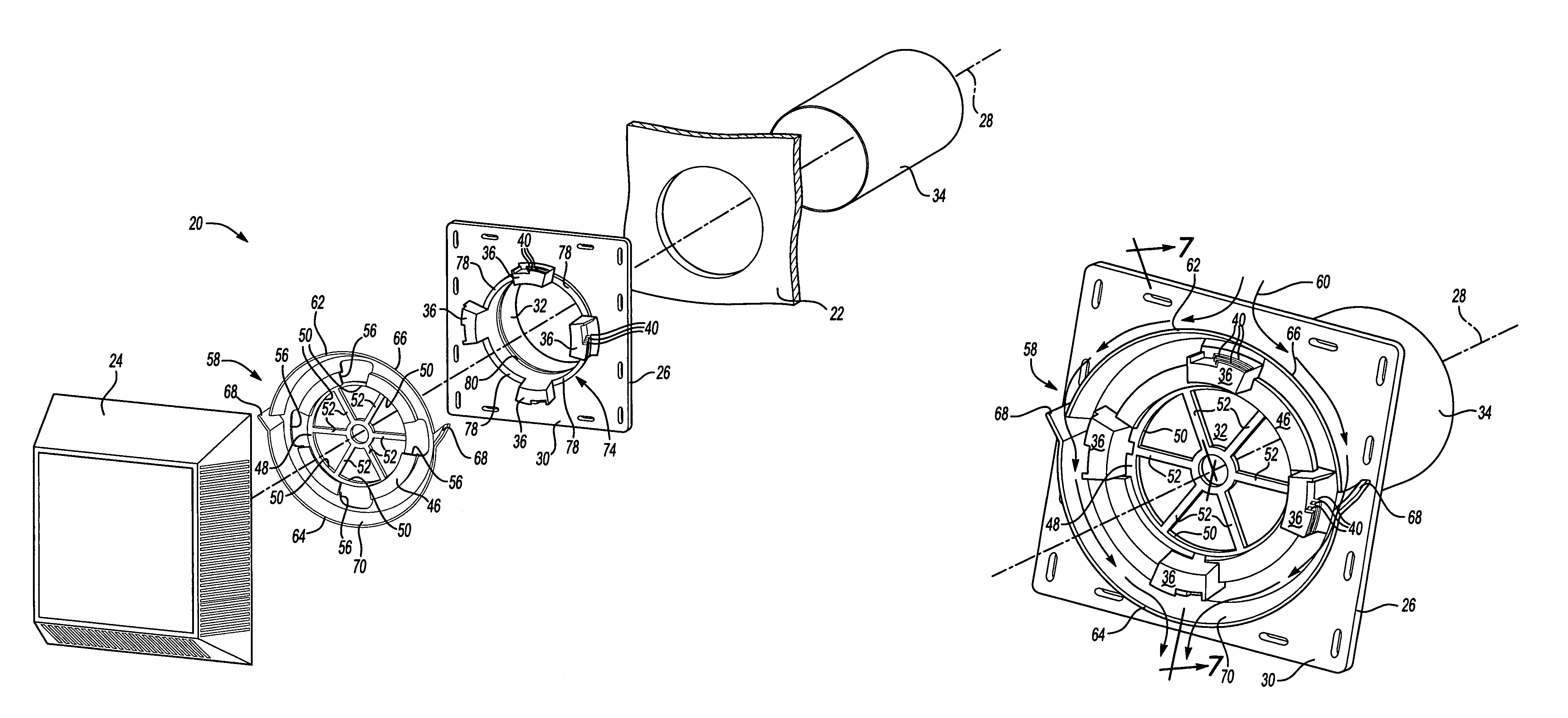
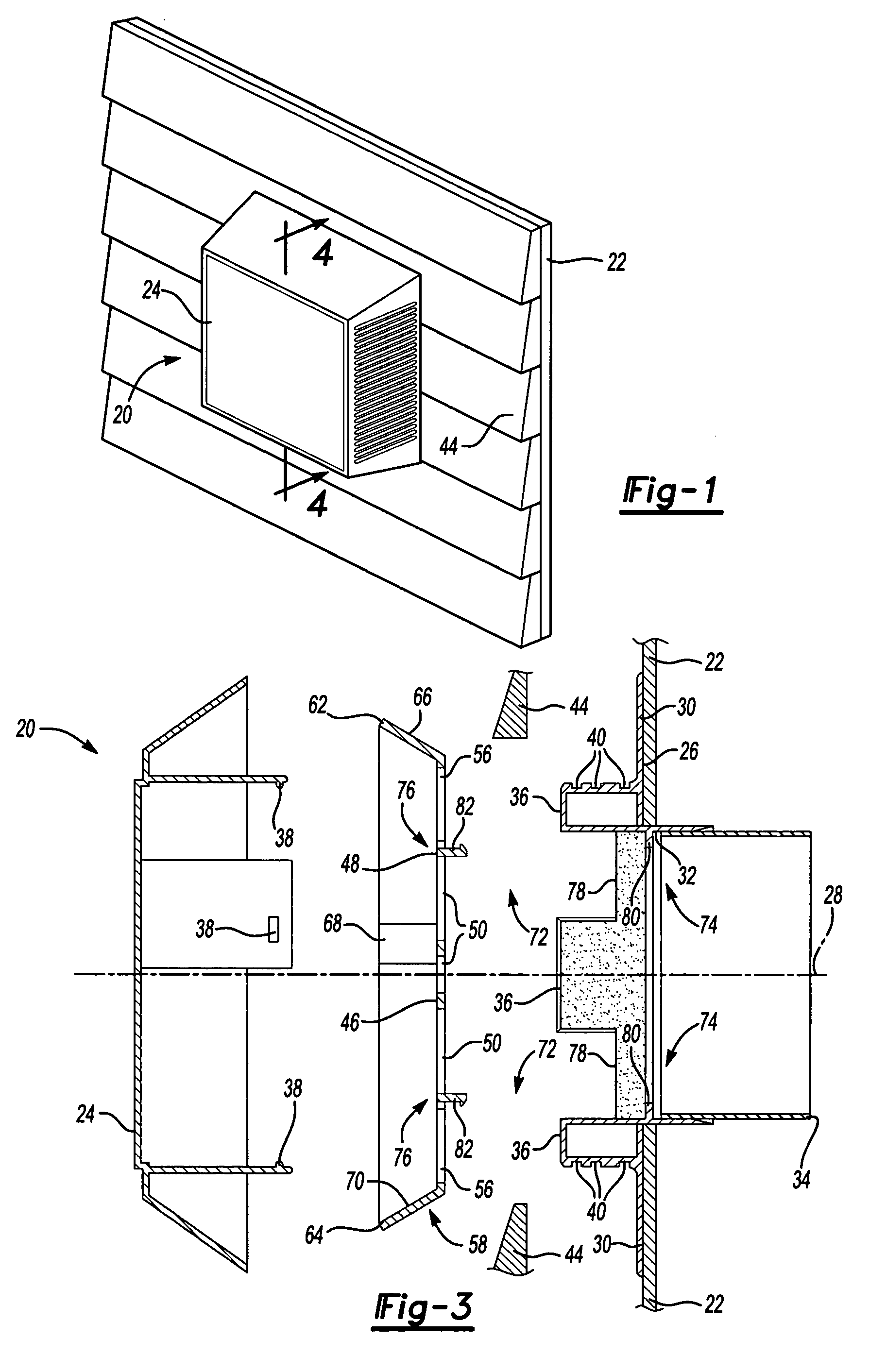
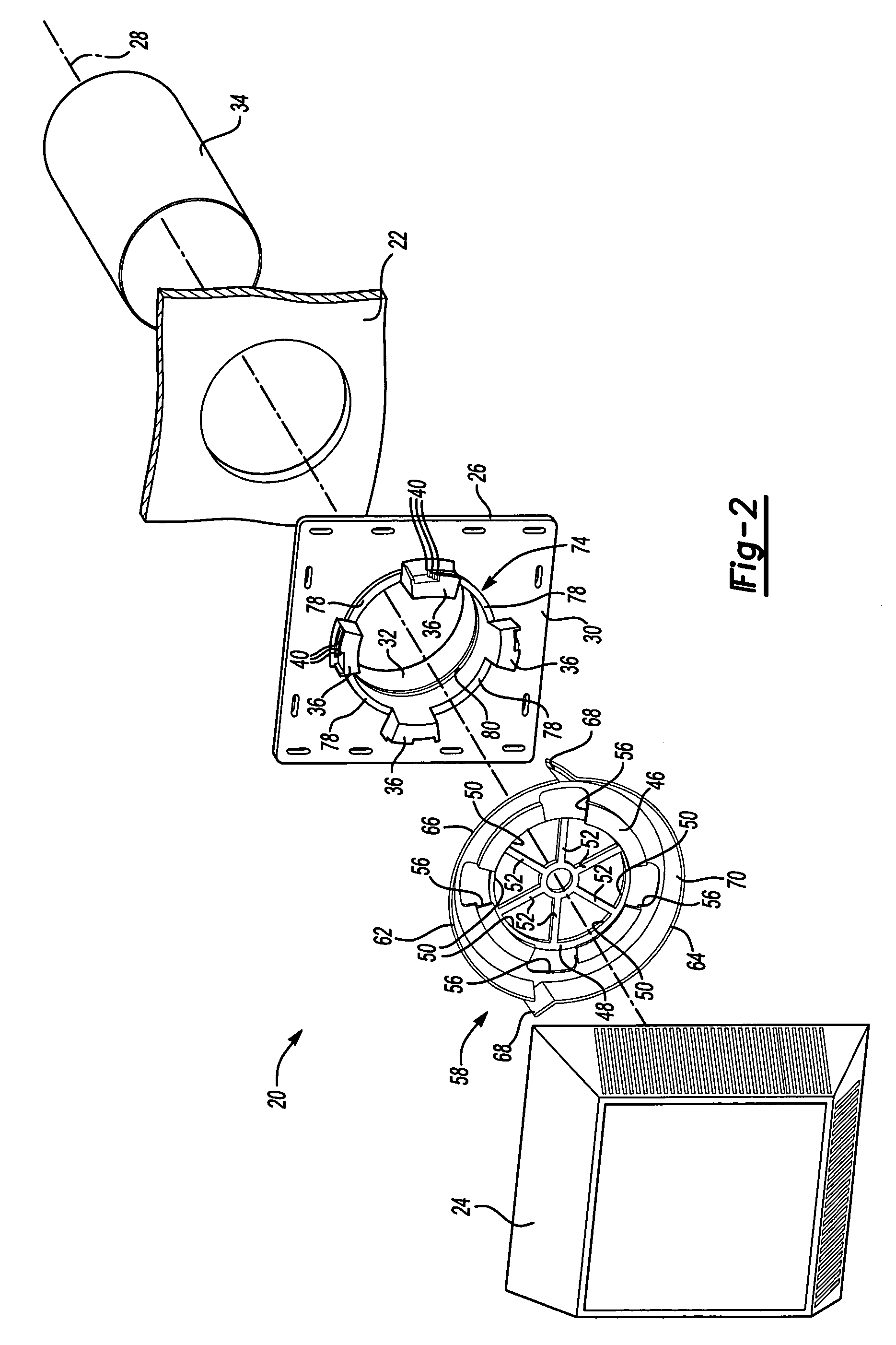
[0018]Referring to the Figures, wherein like numerals indicate corresponding parts throughout the several views, a housing assembly 20 for mounting to a wall 22 of a building (not shown) is generally shown in FIG. 1. Typically, the housing assembly 20 is used to ventilate the building. However, it is to be appreciated that the housing assembly 20 may be used for an electrical outlet, a light fixture, a plumbing fixture, a decorative assembly, a dryer vent, or any other similar use.

[0019]Referring to FIG. 2, the housing assembly 20 includes a front plate 24 and a back plate 26. The front plate 24 is attached to the back plate 26 for aesthetic purposes. The back plate 26 defines an axis 28 and includes a flange 30 extending radially away from the axis 28 for coupling the housing assembly 20 to the wall 22. The back plate 26 further defines a void 32 disposed along the axis 28 in which the flange 30 extends radially away from the void 32. An exhaust vent 34 is disposed in the void 32 f...


PUM


Abstract

A housing assembly for mounting to a wall of a building is disclosed. The housing assembly includes a front plate attached to a back plate. The back plate defines an axis and has a flange extending radially away from the axis for coupling to the wall. An insert is disposed between the front plate and the back plate. The insert includes a central body having a fluid diverter extending outwardly from the central body for guiding a fluid away from the wall. The housing assembly further includes a locking device for selectively coupling and uncoupling the insert from one of the front plate and the back plate.

Description

CROSS REFERENCE TO RELATED APPLICATION[0001]This application claims the benefit of U.S. provisional patent application Ser. No. 60 / 678,026, which was filed on May 5, 2005.BACKGROUND OF THE INVENTION[0002]1. Field of the Invention[0003]The present invention relates to a housing assembly for mounting to a wall of a building.[0004]2. Description of the Prior Art[0005]Various housing assemblies having fluid diverters for redirecting a fluid away from a wall of a building are known in the art. Such an assembly is disclosed in U.S. Pat. No. 6,951,081 (the '081 patent) to Bonshor. The '081 patent discloses a housing assembly having a front plate and a back plate attached to one another and disposed on a wall of a building. The back plate defines an axis and includes a flange extending radially away from the axis for coupling to the wall. The flange includes a fluid diverter for guiding a fluid away from the wall of the building. However, the fluid diverter is permanently attached to the ba...

Claims


Application Information

Patent Timeline
Patent Type & Authority Patents(United States)
IPC IPC(8): E04D13/00E04B1/70F24F13/08F24F7/00
CPCF24F7/00F24F13/082F24F2007/003F24F2007/0025
Inventor LAJEWSKI, TODD M.
Owner TAPCO INTERNATIONAL CORPORATON
Learn More