
Heat transfer plate, plate pack and plate heat exchanger

Inactive Publication Date: 2009-10-27
ALFA LAVAL CORP AB
View PDF15 Cites 0 Cited by
  • Summary
  • Abstract
  • Description
  • Claims
  • Application Information

AI Technical Summary

Benefits of technology

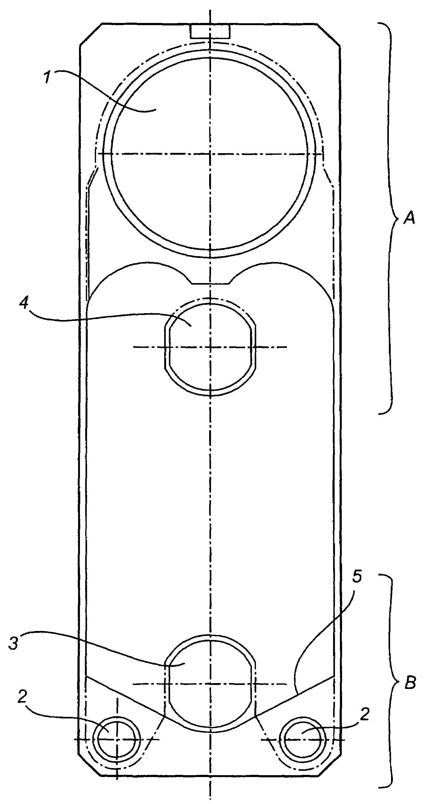
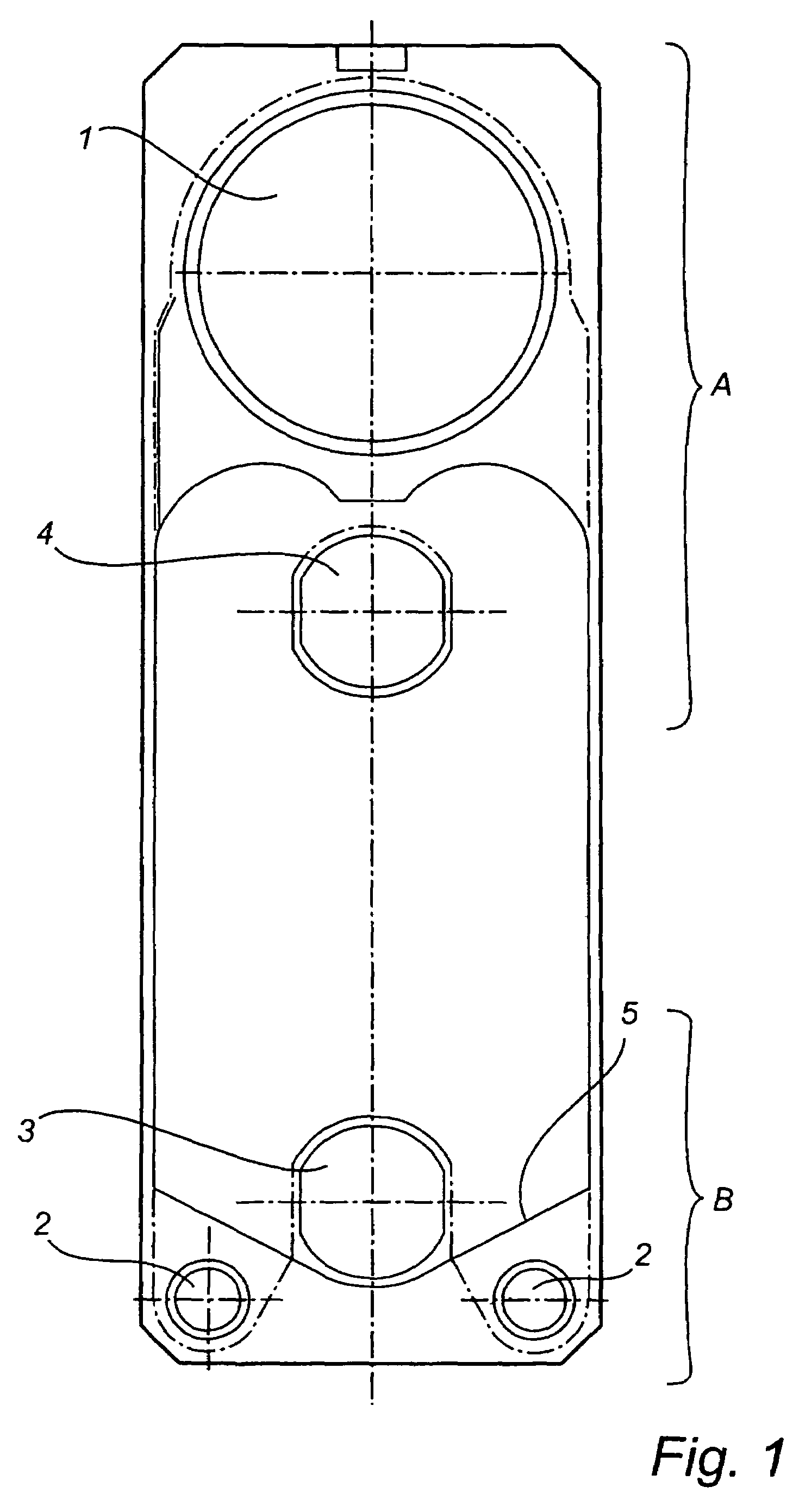
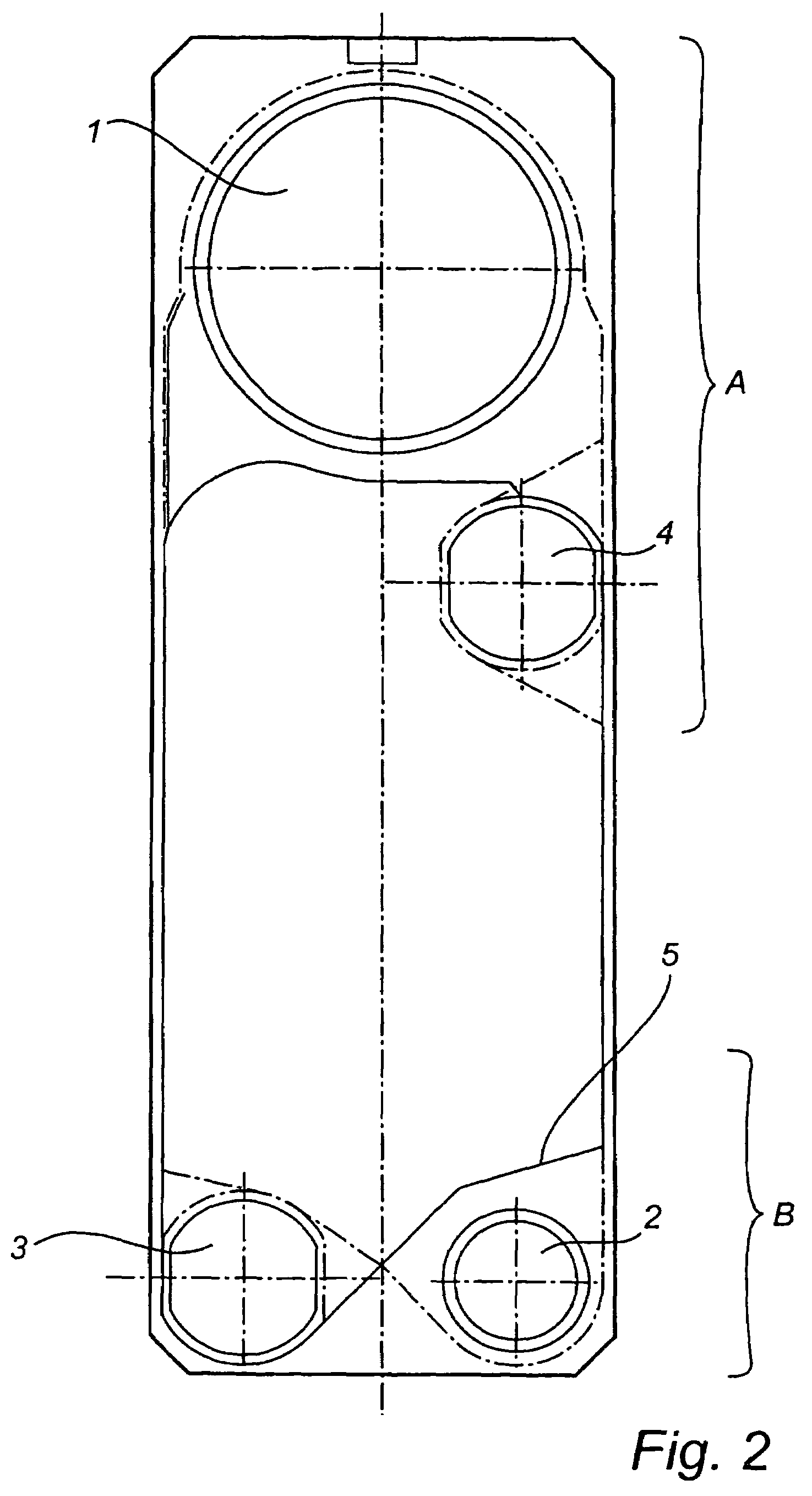
[0016]By designing the heat transfer plate in this manner, an extremely advantageous utilisation of the sheet-metal is obtained as well as a very high degree of efficiency of the condenser or evaporator. The large vapour port extending over essentially the whole width of the plate provides a vapour flow in which essentially no drop in pressure occurs. By arranging the port for the second fluid in the first port portion between the vapour port and the second port portion, benefit may be derived from the fact that, in connection with the phase change, only a relatively short distance is required in the direction of flow where the heat exchange takes place. By arranging the ports in two opposite port portions, the intermediate plate area is optimally utilised to achieve the desired heat exchange.
[0027]Advantageously, each of the plate interspaces in the first set has a channel height or volume that is greater than each of the plate interspaces in the second set. This allows a high degree of efficiency to be obtained. The vapour pressure drop will be small and a large amount of vapour can be supplied, which is desirable since the vapour has a considerably larger volume than a liquid. Moreover, the second fluid will be subjected to a greater pressure drop, the second fluid flow will be more turbulent and the heat transfer more efficient.

Problems solved by technology

In the case of temperatures below 100° C. vapour traps do not work for natural reasons—no pressure can be achieved below atmospheric pressure.
Conventional plate heat exchangers are not very well adapted for this task because of their symmetric design; ports of the same size and the same channel characteristic in both channels.
In applications of this kind, the plates should have relatively large vapour ports to prevent the vapour phase pressure drop at the port or ports from becoming too great, which would have a detrimental effect on the efficiency of the heat exchanger.
This implies poor utilisation of the sheet-metal, which in turn makes the plate heat exchanger too expensive.
However, in this construction the frame plates must be of considerable size, since they need to extend over the whole width of the plate as well as the protrusions.
Nor does the design disclosed in U.S. Pat. No. 4,523,638 satisfy the design requirements stated above regarding efficient utilisation of the sheet-metal.
This particular type of condenser is intended for processes involving heat sensitive products, such as fruit juice, unrefined sugar solutions or the like, and does not provide any solution to the problems related above.

Method used


Image

  • Heat transfer plate, plate pack and plate heat exchanger
  • Heat transfer plate, plate pack and plate heat exchanger
  • Heat transfer plate, plate pack and plate heat exchanger

Examples


Embodiment Construction

[0032]As shown in FIGS. 1 and 2, the heat transfer plate according to the preferred embodiments has a long and narrow, essentially rectangular shape. A port portion A, B is provided on both short sides. In the respective port portions through holes, called ports 1-4, are provided. These heat transfer plates are adapted to be assembled into a plate pack in conventional manner, so that each of the ports forms a channel extending through the plate pack of the plate heat exchanger (not shown).

[0033]For the sake of simplicity, the heat transfer plates described below will be adapted for use in applications in which the fluid undergoing a phase change changes from vapour to condensate. In other words, the heat transfer plates described will be adapted for use in a condenser. For the opposite phase change, i.e. from liquid to vapour (evaporator), the heat transfer plates will have essentially the same design.

[0034]The first port 1 forms a first inlet channel, which is intended for a first ...


PUM


Abstract

A heat transfer plate for a plate heat exchanger has a first port portion (A), a second port portion (B), and a heat transfer portion, which is disposed between the port portions (A, B). The first port portion (A) has a first vapor inlet port (1) which is intended for a first fluid in vapor form and which extends over essentially the whole width of the plate. The second port portion (B) has at least one first outlet port (2), which is intended for condensed vapor. The first port portion (A) has a second outlet port (4), which is disposed between the vapor inlet port (1) and the second port portion (B) and which is intended for a second fluid. The second port portion (B) has a second inlet port (3), which is intended for the second fluid.

Description

FIELD OF THE INVENTION[0001]The present invention relates to a heat transfer plate for a plate heat exchanger, comprising a first port portion which is disposed in one edge portion of the heat transfer plate, a second port portion which is disposed in a second edge portion of the heat transfer plate, and a heat transfer portion which is disposed between said port portions. The invention also relates to a plate pack and a plate heat exchanger.BACKGROUND ART[0002]A plate heat exchanger comprises a plate pack consisting of a number of assembled heat transfer plates forming between them plate interspaces. Generally, every second plate interspace communicates with a first inlet channel and a first outlet channel, each plate interspace being adapted to define a flow area and to conduct a flow of a first fluid between said inlet and outlet channels. Correspondingly, the other plate interspaces communicate with a second inlet channel and a second outlet channel for a flow of a second fluid....

Claims


Application Information

Patent Timeline
IPC IPC(8): F28F3/08F28F3/00F25B39/00F28D9/00F28F1/00
CPCF28B1/02F28D9/005F28D2021/0064F28D2021/0063
Inventor BLOMGREN, RALF
Owner ALFA LAVAL CORP AB
Learn More