Three-stage membrane gas separation process

a gas separation and membrane technology, applied in the field of gas separation membranes, can solve the problems of not meeting the desired composition and recovery specifications, adversely changing the membrane permeation characteristics, and affecting the performance of the membrane, so as to reduce the downtime for maintenance or repair, and improve the recovery of methane.

Active Publication Date: 2009-10-20
MEMBRANE TECH & RES +1
View PDF17 Cites 28 Cited by
  • Summary
  • Abstract
  • Description
  • Claims
  • Application Information

AI Technical Summary

Benefits of technology

[0027]Because the membranes used in each stage preferentially reject methane, the residue streams from all three stages are enriched in methane compared with the feed streams to the respective stages. To minimize methane loss, the residue streams from the second and third stages are usually recirculated within the process. The second residue stream can be returned and mixed with the first feed stream and the third residue stream can be returned and mixed with the first-stage permeate stream.
[0036]The ability of the third stage to improve methane recovery without necessitating the use of a second compressor is beneficial both in terms of the technical performance of the system and the economics of gas treatment. The process is operated with only one set of rotating equipment, thereby decreasing downtime for maintenance or repairs.

Problems solved by technology

Despite the many advances that these patents represent, it is still difficult under field conditions to meet desired composition and recovery specifications.
One problem is that carbon dioxide readily sorbs into and interacts strongly with many polymers, swelling or plasticizing the membrane, and thereby adversely changing the membrane permeation characteristics.
Such membranes can reduce the carbon dioxide content of the treated, residue gas stream to a target value of, for example, 2%, but, because the selectivity is modest, unacceptable quantities of methane will permeate with the carbon dioxide, and will be lost in the permeate stream.
Separation of nitrogen from methane by means of membranes also remains of limited utility because of very low selectivities.
As with carbon dioxide separation, unacceptable losses of methane into the permeate stream occur.
The need for interstage compression greatly increases the capital cost of the membrane system.
The introduction of the compression step also affects the operating costs, as the power requirements and maintenance costs are likely to be higher.
Further, the addition of a second membrane stage may not raise the methane recovery to the point that treatment of the raw gas becomes worthwhile.
For these reasons, much potentially valuable natural gas remains in the ground unexploited, awaiting better treatment technology.

Method used


Image

  • Three-stage membrane gas separation process
  • Three-stage membrane gas separation process
  • Three-stage membrane gas separation process

Examples


example 1

Nitrogen Removal, 8% Nitrogen Concentration

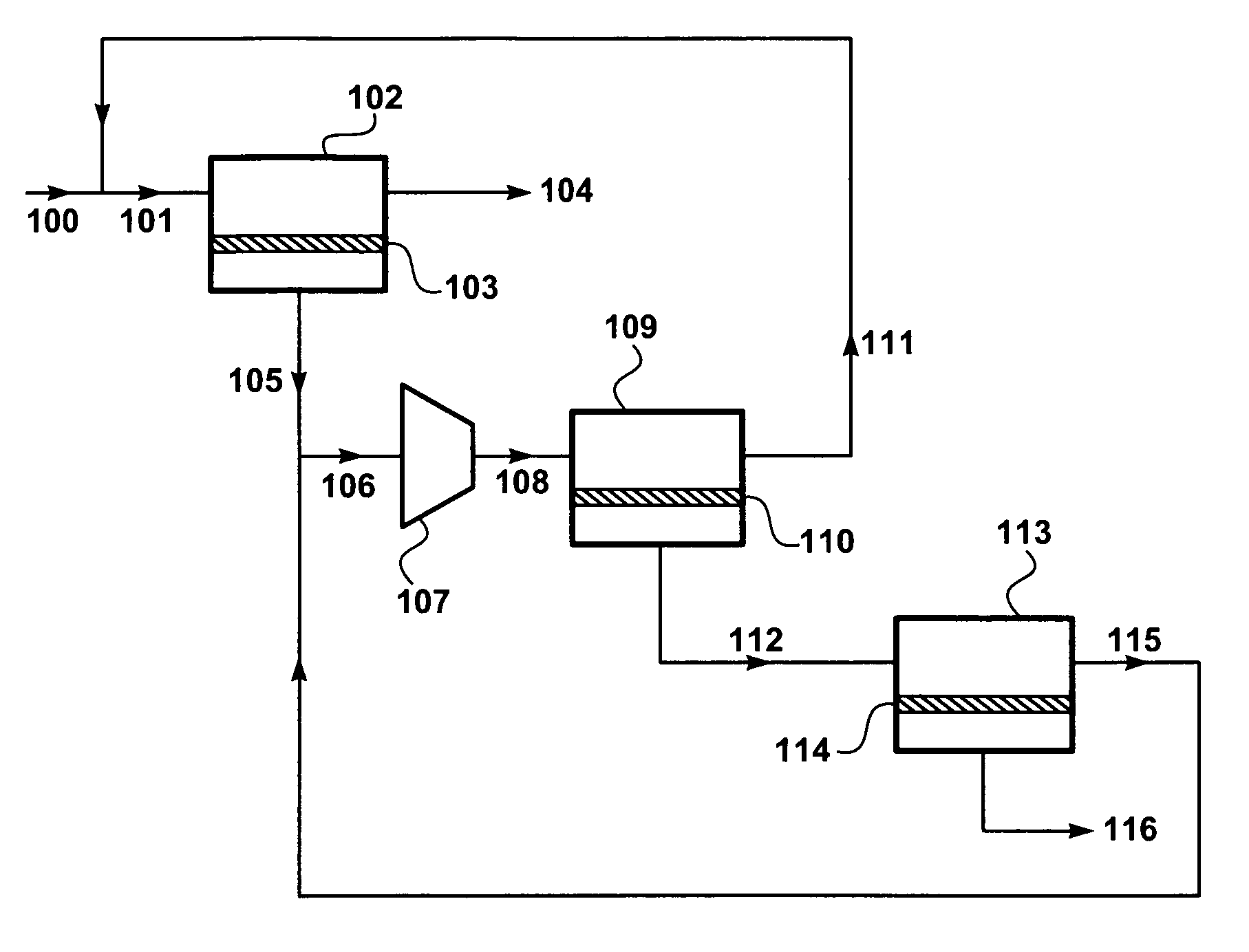
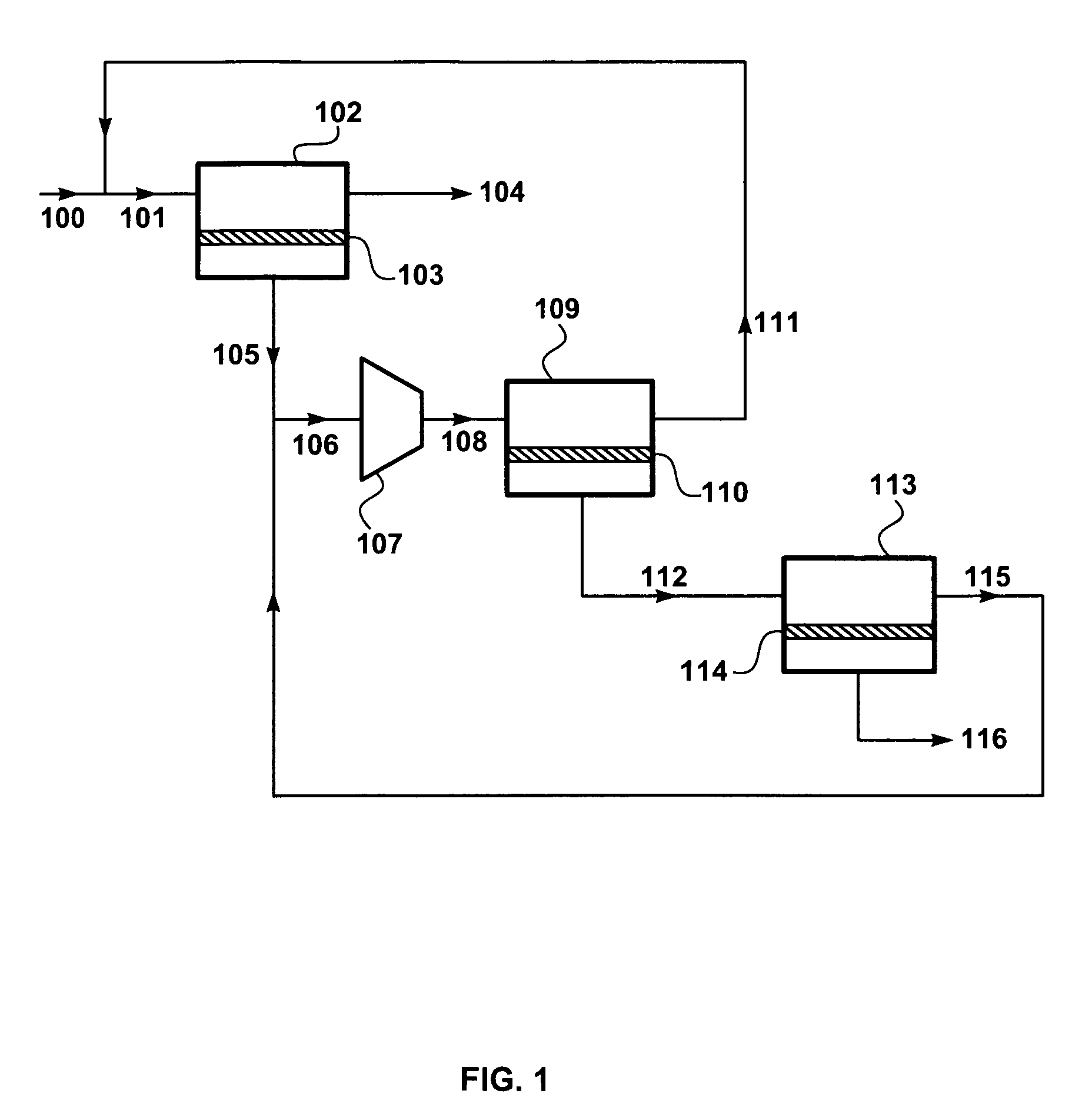
[0109]A computer calculation was performed with a modeling program, ChemCad V (ChemStations, Inc., Houston, Tex.), to demonstrate the process of the invention in a basic embodiment to separate nitrogen from methane, as in FIG. 1.

[0110]The calculation assumed that raw gas stream 100 has a flow rate of 1 MMscfd, contains 8% nitrogen, and is delivered to the process at 30° C. and 500 psia. The target for the process was to reduce the nitrogen content of the first residue stream to 4%.

[0111]It was assumed that each membrane stage contains a membrane having a fluorinated dioxole selective layer and providing a permeance for nitrogen of 50 gpu and a permeance for methane of 20 gpu, so that the nitrogen / methane selectivity is 2.5. The permeate pressures for the first and second membrane stages were assumed to be set at 150 psia, and the first permeate was assumed to be recompressed to 500 psia, so that the pressure ratio in the first and second st...

example 2

Nitrogen Removal, 15% Nitrogen Concentration

[0117]The calculation of Example 1 was repeated, this time assuming that raw gas stream 100 contains 15% nitrogen at 30° C. and 500 psia. Other assumptions were the same as Example 1.

[0118]The results of the calculations are summarized in Table 2.

[0119]

TABLE 2Stream104116100TREATEDTREATEDFEED101RESIDUE105108111112115PERMEATETemp (° C.)3029152111929292828Pressure (psia)5005005001505005001501515Flow rate (MMscfd)1.05.10.74.45.04.10.820.490.33Component (vol %):Methane858596838385748362Nitrogen15154.0171715251738

[0120]As can be seen, the process of the invention was again able to meet the target of 4% nitrogen in the first residue stream, 104. The third permeate stream in this case contains 38% nitrogen, and the methane recovery is about 80%. A higher methane recovery would be possible under the same process operating conditions if the membrane selectivity were slightly higher.

example 3

Carbon Dioxide Removal, Comparative Calculations

[0121]Three computer calculations were performed to model the treatment of a raw natural gas stream that is out of specification with respect to carbon dioxide. The calculations compare the performance of the process of the invention with a process using only two membrane separation stages and with a process using three stages, with compression between the stages.

[0122]In all cases, the raw gas entering the process was assumed to have the following composition:

[0123]

Methane:90.1%Carbon dioxide:5.1%Balance4.8%(C2+ hydrocarbons / / nitrogen / water vapor):

and to be at a pressure of just under 1,000 psia. The calculations were carried out assuming that the same amount of membrane area was available for each separation stage in each calculation. In all cases, the goal was to reduce the carbon dioxide content of the gas to 2%. For the first calculation, according to the process of the invention, the raw gas flow rate was assumed to be about 6 MM...


PUM


Abstract

A process for removing carbon dioxide or nitrogen from gas, especially natural gas. The process uses three membrane separation stages without compression between the second and third stages.

Description

FIELD OF THE INVENTION[0001]The invention relates to the use of gas separation membranes to remove excess carbon dioxide or nitrogen from gas, particularly natural gas.BACKGROUND OF THE INVENTION[0002]Natural gas is the most important fuel gas in the United States and provides more than one-fifth of all the primary energy used in the United States. Natural gas is also used extensively as a basic raw material in the petrochemical and other chemical process industries. The composition of natural gas varies widely from field to field. For example, a raw gas stream may contain as much as 95% methane, with only minor amounts of other hydrocarbons, nitrogen, carbon dioxide, hydrogen sulfide or water vapor. On the other hand, streams with large proportions of one or more of these contaminants are common. For example, gas that is extracted as a result of miscible flood enhanced oil recovery may be very rich in carbon dioxide, as well as being saturated with C3+ hydrocarbons.[0003]Overall, a...

Claims


Application Information

Patent Timeline
Patent Type & Authority Patents(United States)
IPC IPC(8): B01D53/22
CPCB01D53/226B01D69/02B01D71/44Y02C10/10B01D2257/504B01D2325/20B01D2256/10Y02C20/40
Inventor MALSAM, MICHAEL G.LOKHANDWALA, KAAEID A.
Owner MEMBRANE TECH & RES
Why Eureka
Try Eureka