
Schiefspiegler telescope with three reflecting surfaces

a technology of reflecting surfaces and telescopes, applied in telescopes, microscopes, mountings, etc., can solve the problems of unsolved increase in adjustment expenditure, unresolved adjustment of mirrors and angular settings, and central vignetting contrast reduction, etc., to achieve simple adjustment of reflecting surfaces and simple construction

Inactive Publication Date: 2009-10-13
JENA-OPTRONIK
View PDF12 Cites 5 Cited by
  • Summary
  • Abstract
  • Description
  • Claims
  • Application Information

AI Technical Summary

Benefits of technology

[0012]It is the primary object of the invention to find a novel possibility for realizing a reflector telescope without vignetting (Schiefspiegler) which permits a simple construction and a simple adjustment of the reflecting surfaces relative to one another. A further object is to enable repeatedly rotating scanning (imaging).
[0020]In the light path of the input beam bundle to the off-axis beam bundle, at least one depolarizer is advantageously arranged in front of the input deflecting mirror in order to reduce the polarization sensitivity within the telescopic imaging. This is particularly important when scenes to be imaged reflect partially or primarily polarized light (e.g., water surfaces or glass surfaces, etc.).
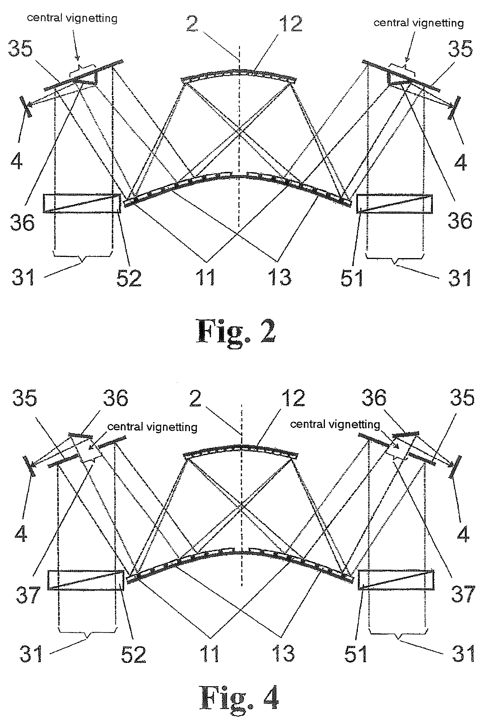
[0022]The invention is based on the consideration that Schiefspiegler telescopes are costly to adjust and are exposed to the risk of subsequent disadjustment by environmental influences. A symmetric mirror arrangement would be desirable for simplification. The desire for a symmetric construction and error-free optical imaging of a scene by means of an adjustable two-mirror, rotationally symmetric on-axis telescope which is operated optically as a three-reflector Schiefspiegler are bridged in a surprisingly compact manner in that the primary mirror and the tertiary mirror are portions of one and the same mirror base surface (carrier surface). This is advantageous for the manufacture as well as for the adjustment of the telescope. Equivalent optical images can be realized in different (preferably, but not necessarily, opposed) directions through the axis of symmetry. Oppositely extending off-axis beam bundles within a plane are particularly suitable for enabling a simple rotating scanning system.
[0023]With the solution according to the invention it is possible to implement a reflector telescope without vignetting (Schiefspiegler) which permits a simple construction and a simple adjustment of the reflecting surfaces relative to one another. Further, a rotating scanning (imaging) enabling application in radiometers can be realized in an uncomplicated manner.

Problems solved by technology

Reflector telescopes of conventional construction in a rotationally symmetric mirror configuration (e.g., the systems of Gregory, Cassegrain and Newton) which are standard above all for astronomical observation suffer from contrast-reducing central vignetting due to the secondary mirror located in the beam path and the holding braces which are usually provided for it.
However, asymmetric mirror systems which are tilted parallel to a plane are used, and the problem of increased expenditure on adjustment remains unsolved.
While the adjustments of the mirrors and angular settings within a plane are limited, the overall arrangement is still costly as concerns minimizing imaging errors.

Method used


Image

  • Schiefspiegler telescope with three reflecting surfaces
  • Schiefspiegler telescope with three reflecting surfaces
  • Schiefspiegler telescope with three reflecting surfaces

Examples


Embodiment Construction

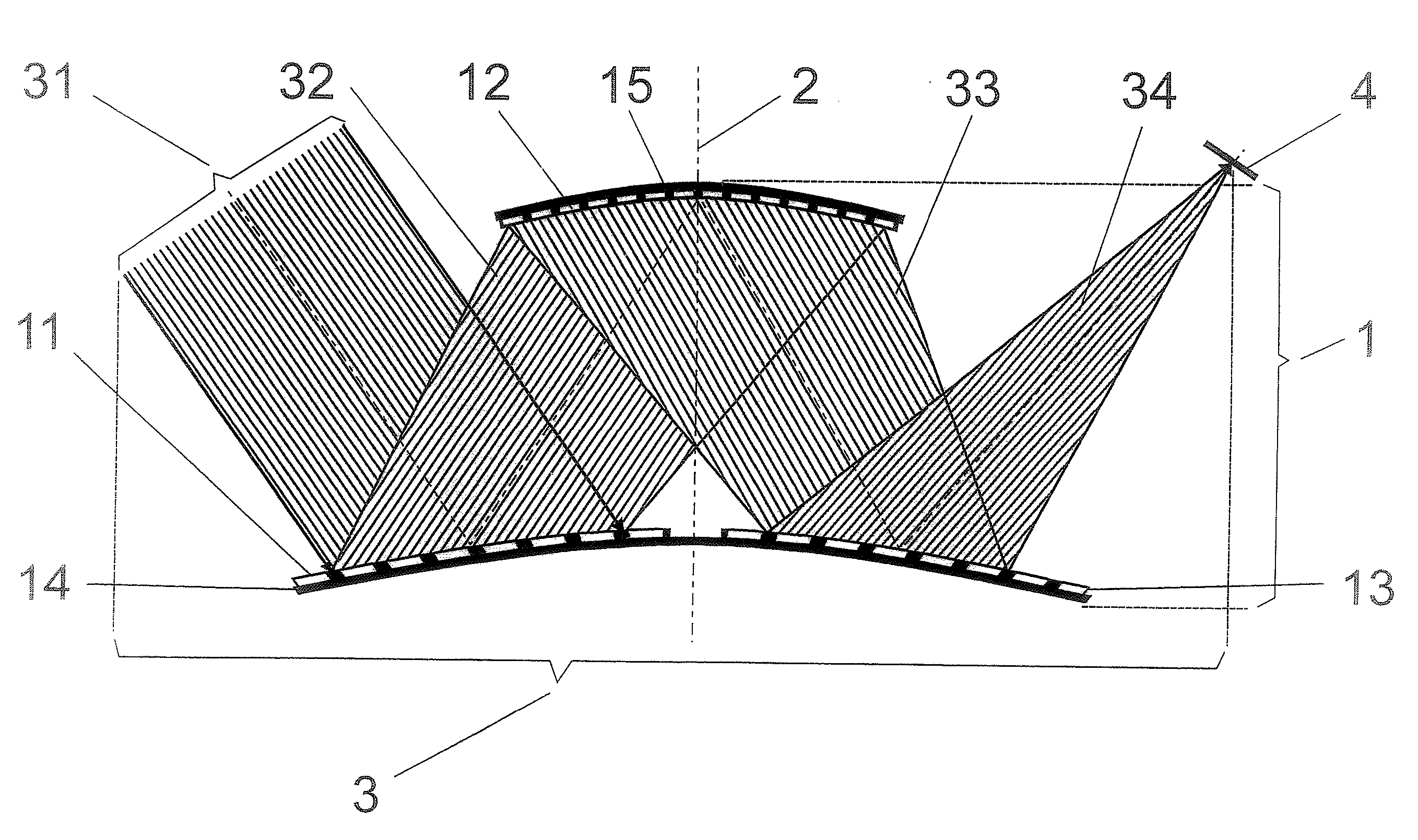
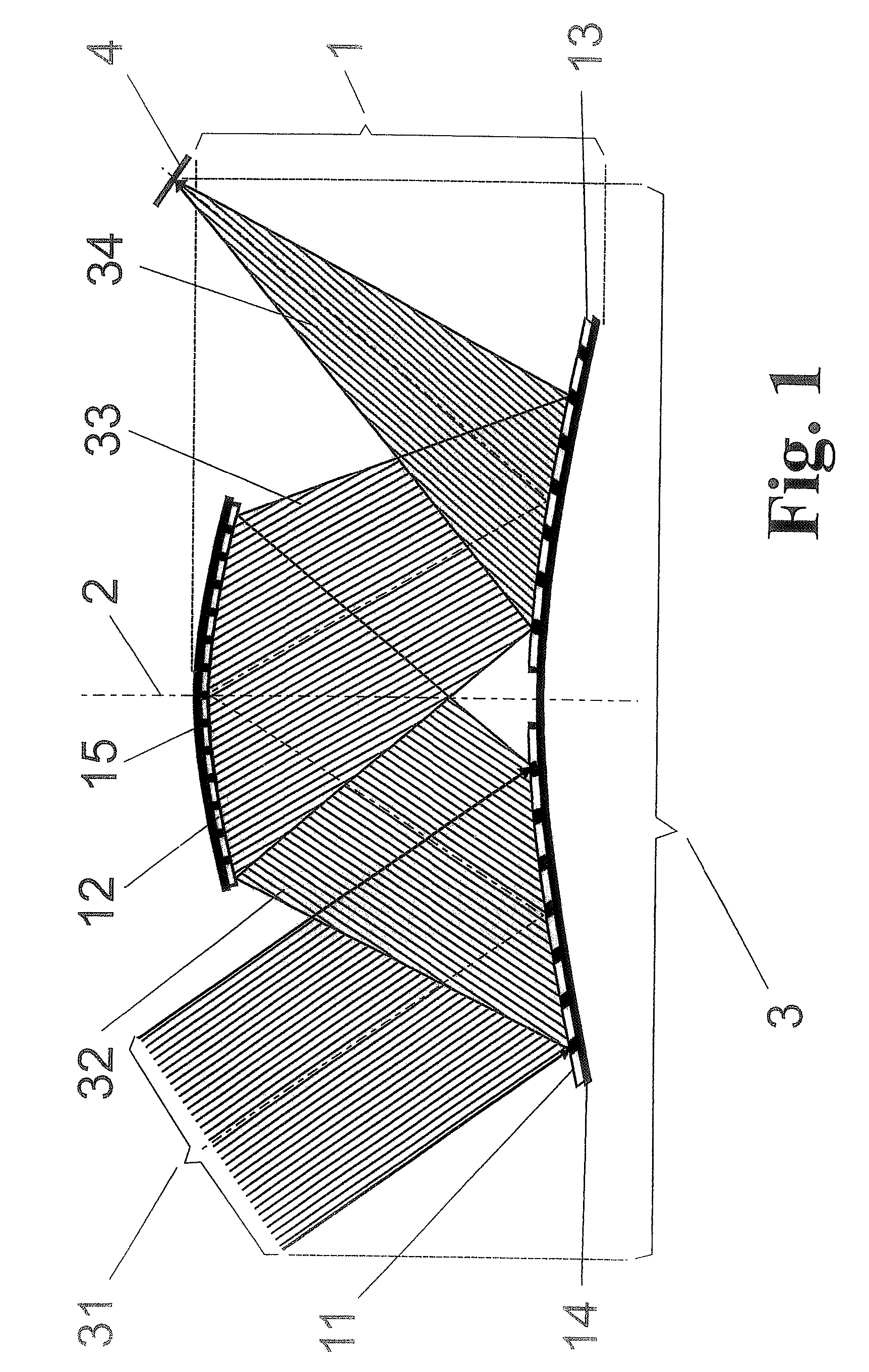
[0031]As is shown in FIG. 1, the Schiefspiegler telescope according to the invention substantially comprises a mirror arrangement 1 which has an axis of symmetry 2 and in which an off-axis beam bundle 3 extends from an input beam bundle 31 along a plane (in this instance, the drawing plane) through the axis of symmetry 2 for imaging on a receiver 4. The off-axis beam bundle 3 uses three reflecting surfaces, a primary reflecting surface 11, a secondary reflecting surface 12, and a tertiary reflecting surface 13. The primary reflecting surface 11 and tertiary reflecting surface 13 lie on the same carrier surface 14 of the mirror arrangement 1 symmetric to the axis of symmetry 2.

[0032]Therefore, the mirror arrangement 1 comprises aspheres which are curved in the same direction along the axis of symmetry 2. The larger carrier surface 14 carries the convex primary reflecting surface 11 and the tertiary reflecting surface 13. The smaller carrier surface 15 located above the latter has the...


PUM


Abstract

A Schiefspiegler telescope with three reflecting surfaces, preferably for observing the earth from space, particularly for imaging radiometers. A novel possibility for realizing a reflector telescope without vignetting which permits a simple construction and a simple adjustment of the reflecting surfaces relative to one another. In a Schiefspiegler telescope with three reflecting surfaces whose mirror axes are arranged within a plane, the primary reflecting surface and tertiary reflecting surface are convex surfaces of identical shape arranged symmetrically with respect to an axis of symmetry. The secondary reflecting surface is arranged symmetric to the primary reflecting surface and tertiary reflecting surface so as to be rotationally symmetric around the axis of symmetry so that all three reflecting surfaces have an axially symmetric mirror arrangement with respect to design in which the optical imaging is transmitted to a receiver in the manner of an off-axis telescope.

Description

CROSS-REFERENCE TO RELATED APPLICATION[0001]This application claims priority of German Application No. 10 2005 044 910.7, filed Sep. 14, 2005, the complete disclosure of which is hereby incorporated by reference.BACKGROUND OF THE INVENTION[0002]a) Field of the Invention[0003]The invention is directed to a Schiefspiegler telescope with three reflecting surfaces in which an optical imaging by means of the three reflecting surfaces takes place extra-axially with respect to their respective center mirror axis, wherein the mirror axes of all of the reflecting surfaces are arranged within a plane. The invention is applied for observing the earth from space, particularly for imaging radiometers.[0004]b) Description of the Related Art[0005]Reflector telescopes of conventional construction in a rotationally symmetric mirror configuration (e.g., the systems of Gregory, Cassegrain and Newton) which are standard above all for astronomical observation suffer from contrast-reducing central vignet...

Claims


Application Information

Patent Timeline
Patent Type & Authority Patents(United States)
IPC IPC(8): G02B23/00
CPCG02B23/06G02B17/0615
Inventor THORWIRTH, GUENTERVOSS, BURKART
Owner JENA-OPTRONIK
Learn More