
Launching device for toy rocket

a technology for rockets and launch devices, which is applied in the direction of toys, weapons, toy aircraft, etc., can solve the problems of rocket “c” with the weight, the rocket “c” tends to tilt and might hurt people around the launch site,

Inactive Publication Date: 2009-10-13
CHANG PING SUNG
View PDF9 Cites 11 Cited by
  • Summary
  • Abstract
  • Description
  • Claims
  • Application Information

AI Technical Summary

Problems solved by technology

However, the cable “A1” is connected the extension “B31” which is offset from the center of the control member “B2” and the rocket “C” so that the rocket “C” tends to tilt and might hurt people around the launching site.
Once the rocket “C” is not launched along the expected path, the rocket “C” with the weight could injure people.

Method used


Image

  • Launching device for toy rocket
  • Launching device for toy rocket
  • Launching device for toy rocket

Examples


Embodiment Construction

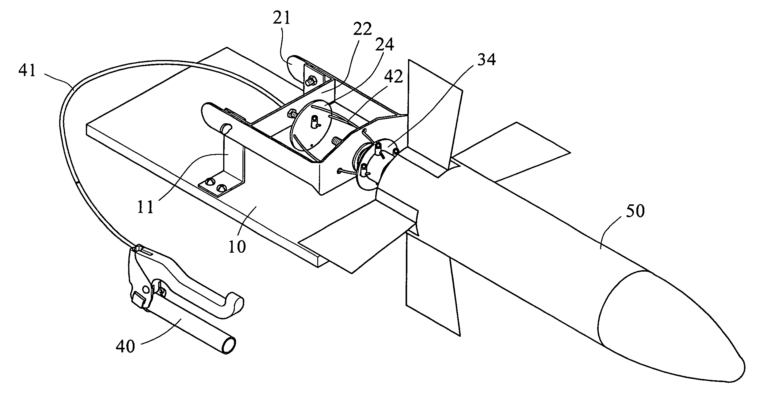
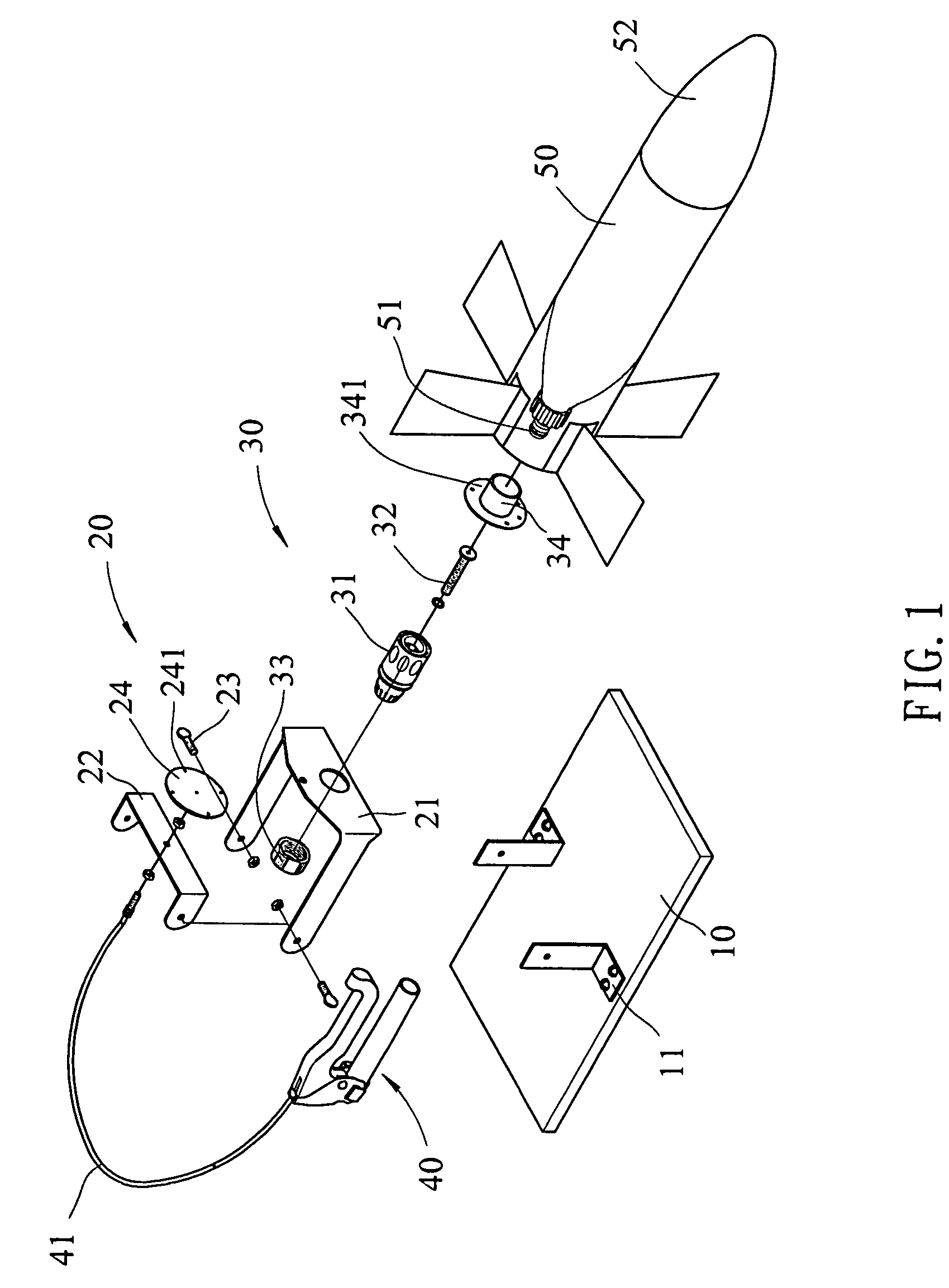
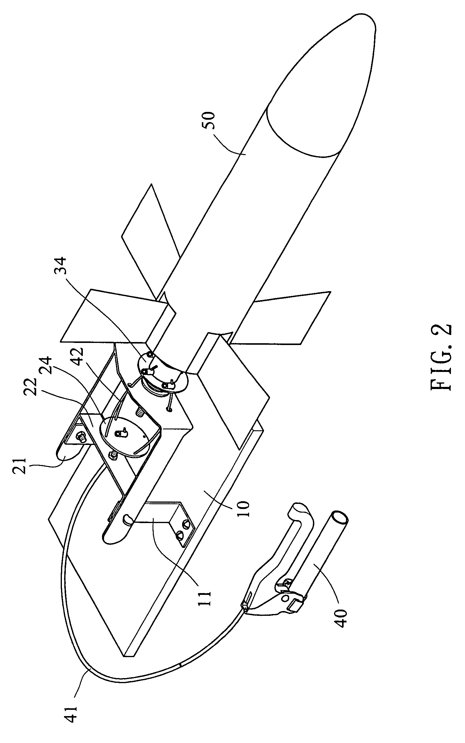
[0017]Referring to FIGS. 1 and 2, the toy rocket launching device of the present invention comprises a stand 10 which is a board and two lugs 11 are connected on a top of the stand 10. A positioning unit 20 includes a U-shaped frame 21 which includes two legs and a transverse portion connected between the two legs, the two legs are pivotably connected to the two lugs 11 on the stand 10. A transverse plate 22 is connected between two legs of the U-shaped frame 21 by bolts 23.

[0018]A control unit 30 includes a control member 31 which has a first end connected to an injection nozzle 51 of a rocket 50 and a second end of the control member 31 extends through the transverse portion of the U-shaped frame 21 and is secured by a threaded sleeve 33. A valve 32 is inserted into the first end of the control member 30 and a cap 34 is mounted on the first end of the control member 31. The valve 32 is engaged with the injection nozzle 51 so that pressurized air can be supplied into the toy rocket...


PUM


Abstract

A toy rocket launching device includes a stand and a positioning unit is pivotably connected to the stand. A control unit includes a control member which has a first end connected to an injection nozzle of the rocket and a second end of the control member extends through a positioning unit and is secured by a threaded sleeve. An valve is inserted into the first end of the control member and a cap is mounted on the first end of the control member. An activation member is located in the positioning unit and multiple balance cables are connected between the activation member and the cap. An end of an activation cable is connected to a center of the activation member so that when the activation cable is pulled, the cap is simultaneously pulled to activate the injection nozzle to lunch the toy rocket.

Description

FIELD OF THE INVENTION[0001]The present invention relates to a launching device for launching a toy rocket operated by pressure and the activation member of the launching device steadily launches the toy rocket.BACKGROUND OF THE INVENTION[0002]A conventional launching device “B” for launching toy rocket from a stand “A” is shown in FIG. 9 and generally includes a control member “B2” which has one end secured on the stand “A” by a threaded sleeve “B1” and the other end of the control member “B2” is connected with the injection nozzle on the rocket “C”. A plate “B3” has one end connected to the control member “B2” and includes an extension “B31” to which one end of a cable “A1” is connected. The rocket “C” is made by a bottle in which a proper pressurized air is filled. When the cable “A1” is pulled, the launching device “B” is activated and the rocket “C” is launched from the stand “A”. However, the cable “A1” is connected the extension “B31” which is offset from the center of the co...

Claims


Application Information

Patent Timeline
Patent Type & Authority Patents(United States)
IPC IPC(8): A63H33/20A63H27/00
CPCA63H27/14A63H27/005
Inventor CHANG, PING-SUNG
Owner CHANG PING SUNG
Learn More