
Recessed lamp structure

a lamp holder and recessed technology, applied in the direction of fixed installation, lighting and heating equipment, lighting support devices, etc., can solve the problem of inability to adapt the lamp holder, achieve the effect of simple and simplified recessed lamp structure, increase the rotation radius of the lamp holder, and effective adjustment of lighting angl

Inactive Publication Date: 2009-10-13
CHEN YEN CHANG
View PDF5 Cites 7 Cited by
  • Summary
  • Abstract
  • Description
  • Claims
  • Application Information

AI Technical Summary

Benefits of technology

"The present invention provides a recessed lamp structure that allows for a larger rotation radius of the lamp holder, which enables effective mounting of the lamp bulb and adjustment of the lighting angle. Additionally, the structure is simplified and easier to assemble, as all components are fixed by the same bolts."

Problems solved by technology

Accordingly, the lamp bulb has a smaller rotation angle, and the lamp holder is not adaptable for the lamp bulb that has a longer length.

Method used


Image

  • Recessed lamp structure
  • Recessed lamp structure
  • Recessed lamp structure

Examples


Embodiment Construction

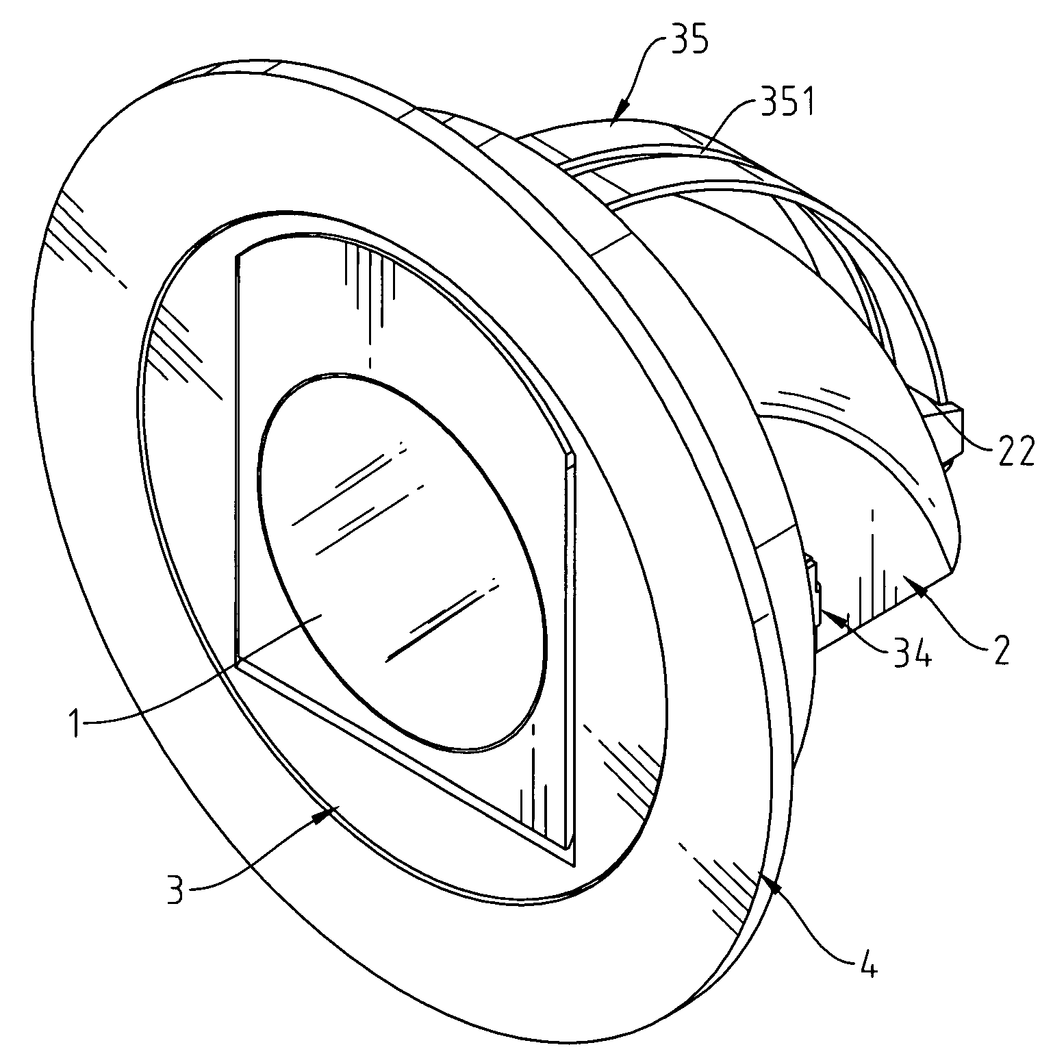
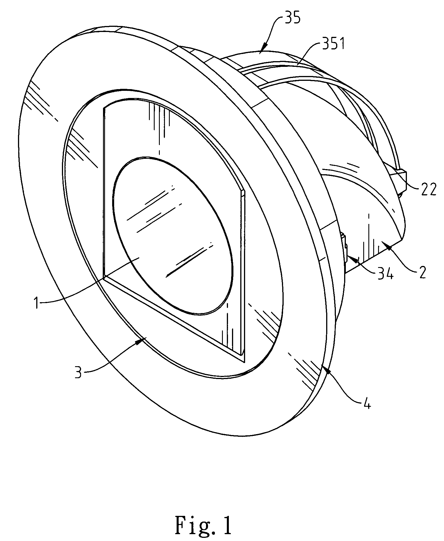
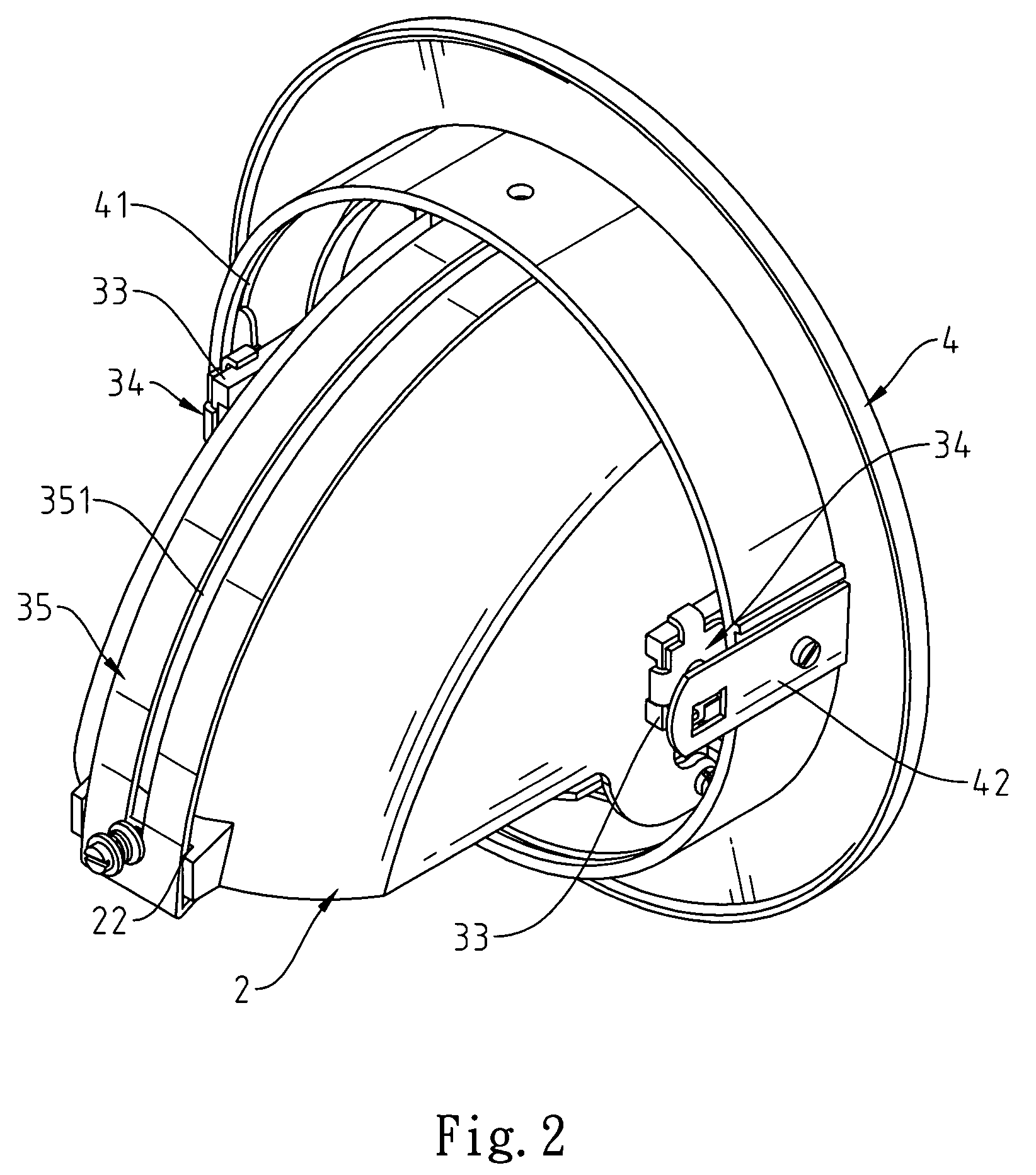
[0013]Referring to FIG. 1 through FIG. 5, a recessed lamp structure of the present invention generally comprises a lamp bulb 1, a lamp holder 2, a rotatory carrier 3, and an outer mounting base 4. The lamp bulb 1 is insertably coupled with a reception head 21 mounted inside the lamp holder 2, wherein the reception head 21 is fixed on the inside of the lamp holder 2 and designed for holding the lamp bulb 1. In addition, the lamp holder 2 further has a runner base 22 and two coupling means 23 disposed oppositely on upper and lower locations of an opening that forms on the rearward of the lamp holder 2. As a result, the lamp holder 2 is rotatable between the rotatory carrier 3 and the outer mounting base 4 by coupling with the rotatory carrier 3.

[0014]The lamp holder 2 is pivotally disposed in the rotatory carrier 3 for adjusting the lighting angle. The rotatory carrier 3 has a coupling base 31 and an axially connecting base 32 disposed oppositely on the front and the back of the rim t...


PUM


Abstract

A recessed lamp structure comprises: a lamp bulb, a lamp holder, a rotatory carrier and an outer mounting base. The rotatory carrier is securely screwed onto a track frame, which has a hollow sliding slot on the center of the bended body thereof. The track frame is securely positioned on the axially connecting base of the rotatory carrier via two axial plates that locate on the rearward of the track frame. The lamp holder is rotatably coupled with the rotatory carrier by two bolts. The bolts are mounted in the limited connection space between the lamp holder and the rotatory carrier. Besides, the lamp holder is shiftable along the sliding slot for adjusting the lighting angle within approximate 70 degrees. Consequently, the recessed lamp structure of the present invention has simplified components and is easy to practice.

Description

FIELD OF THE INVENTION[0001]The present invention relates to a recessed lamp structure, and more particularly to a recessed lamp structure that has a lamp holder for insertion thereinto of a lamp bulb of different lengths so that the lamp holder is smoothly shiftable along a sliding slot for changing the lighting angle.BACKGROUND OF THE INVENTION[0002]As disclosed in U.S. patent application. No. Ser. 11 / 482,742, filed on 2006 by the present inventor, a rotatory carrier 3 has a coupling base 31 and a fixing base 32 disposed oppositely on the backside of the rim thereof. Two paired lateral arms 33 are disposed bilaterally on the rotatory carrier 3. A track frame 35 is fixed on the coupling base 31 and the fixing base 32. A sliding slot 351 is formed on the upper portion of the track frame 35, and the front end of the track frame 35 is fixed on the coupling base 31 of the rotatory carrier 3. The track frame 35 is securely screwed on the fixing base 32 via fixing plates 352 that locates...

Claims


Application Information

Patent Timeline
Patent Type & Authority Patents(United States)
IPC IPC(8): F21V15/00
CPCF21V21/30F21V21/04F21S8/02
Inventor CHEN, YEN-CHANG
Owner CHEN YEN CHANG
Learn More