
Tire pressure monitor system module

a technology of tire pressure monitoring and monitor system, which is applied in the direction of anti-theft devices, tyre measurements, vehicle components, etc., can solve the problems of tire pressure sensing systems that may not operate properly, devices subject to loss, and previous techniques that have been limited in effectiveness

Active Publication Date: 2009-09-22
SPX CORP
View PDF35 Cites 18 Cited by
  • Summary
  • Abstract
  • Description
  • Claims
  • Application Information

AI Technical Summary

Benefits of technology

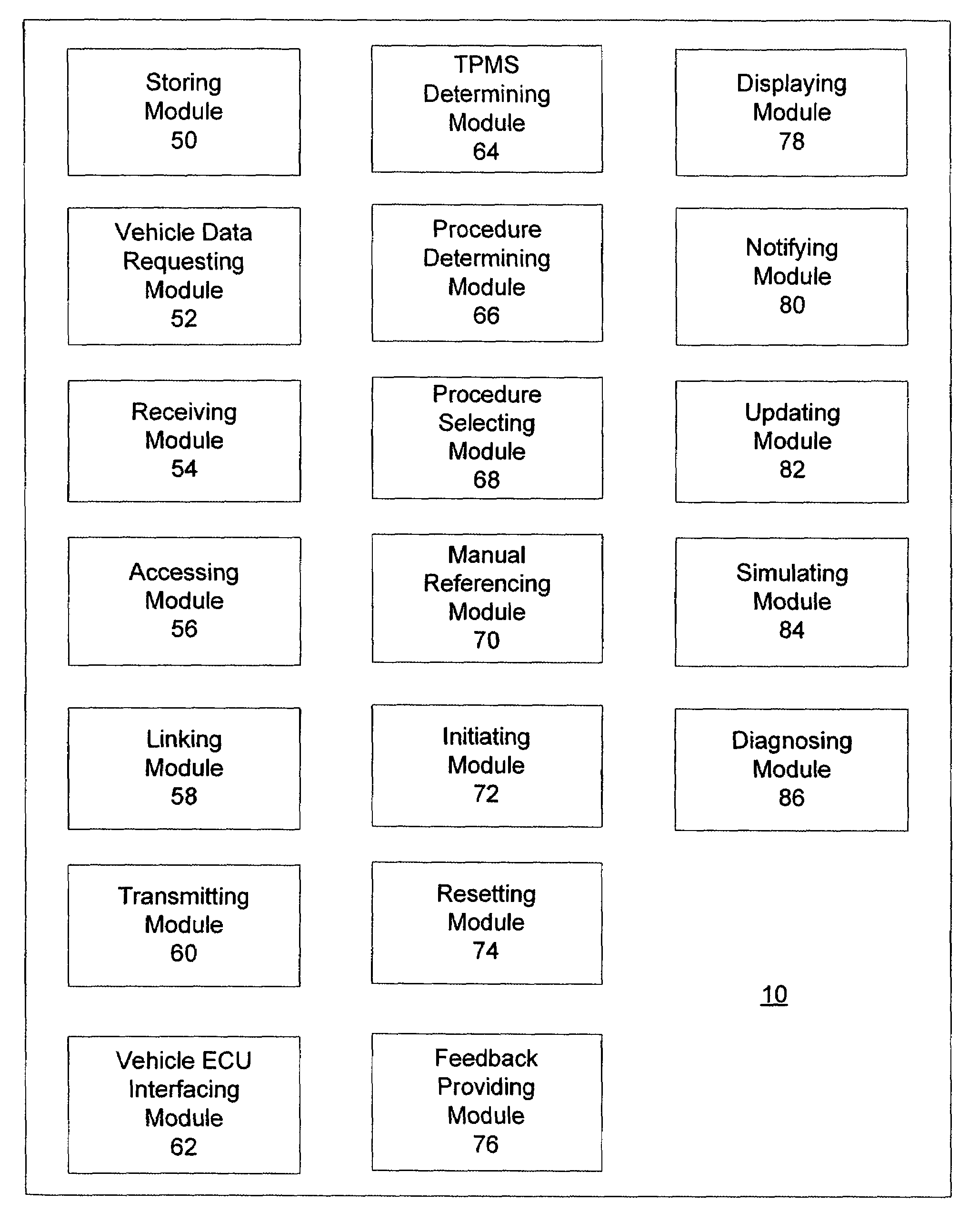
"The invention provides a tire pressure monitor system module that can be added to existing modular products or used as a standalone module. The module includes functionality for transmitting and receiving signals, resetting and diagnosing the system, initiating procedures, and notifying the user of the status of the procedure. The invention also includes a tool that has all the functionality of a tire pressure monitor system, including simulating a sensor, storing and updating information, and notifying the user of the status of a procedure. The invention is not limited to the specific details and arrangements provided and can be implemented in different ways."

Problems solved by technology

One problem with this device is that a separate component such as a magnet must be provided to the vehicle operator that is used only in the calibration process.
One problem associated with a separate magnet device is that such a device is subject to loss.
One problem with such systems is the need to program the location of the transmitters at the central station.
One drawback with such a system is that because many wheels are made from steel which is a magnetic material, tire pressure sensing systems may not operate properly because the steel wheels may shield the magnetic energy.
These previous techniques have been limited in effectiveness.
The magnetic programming technique may be subject to interference and crosstalk, for example in a factory where many such tire monitors are being assembled with tires and vehicles.

Method used


Image

  • Tire pressure monitor system module
  • Tire pressure monitor system module
  • Tire pressure monitor system module

Examples


Embodiment Construction

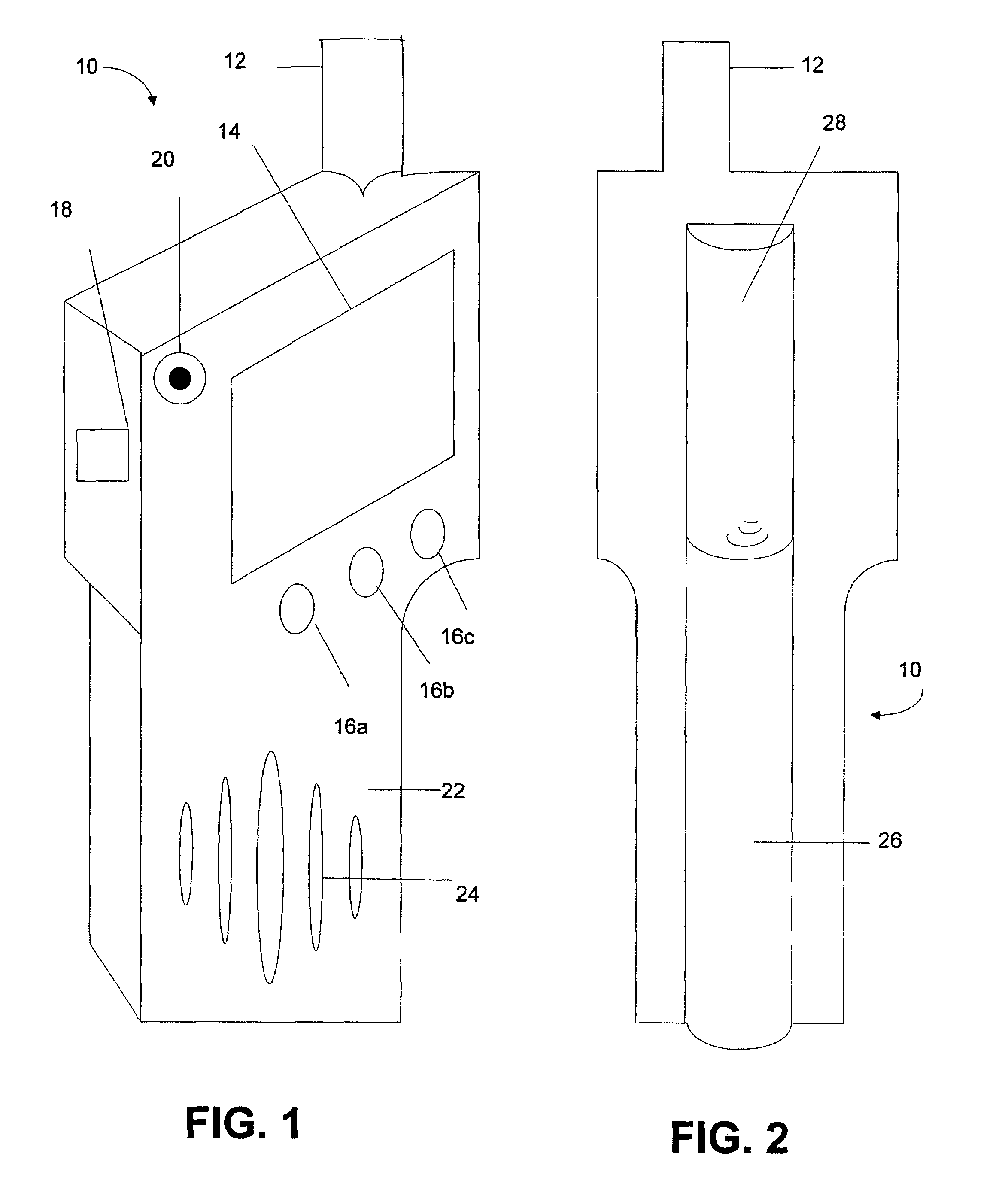
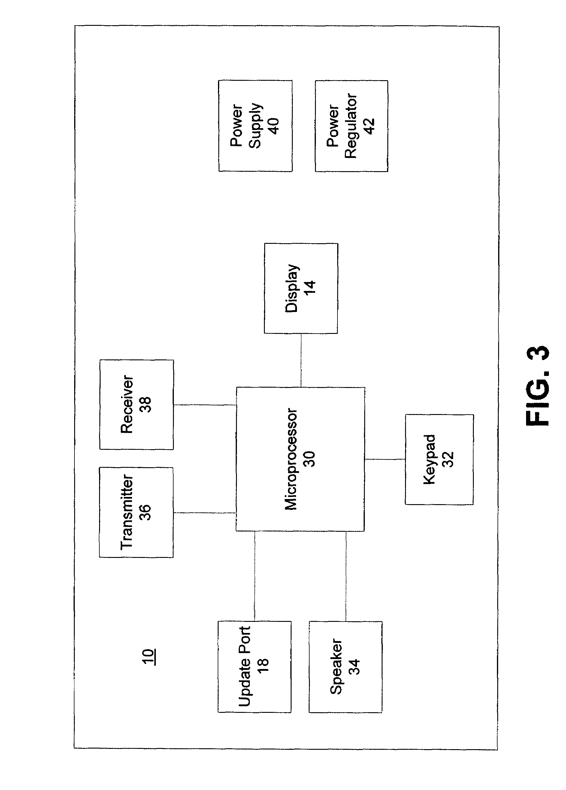
[0027]FIG. 1 illustrates a tire pressure monitor tool 10 according to one embodiment of the invention. The tool 10 includes an antenna 12, display 14, selector button 16a-16c, port 18, a power button 20, a casing 22, and passages 24. The antenna 12 may be used to transmit signals from the tool 10 to an electronic control unit of a vehicle and a tire pressure sensor mounted, for example, on a rim or tire of a vehicle. The display 14 may be used to display information to a user regarding, for example, the tool 10, a tire pressure monitor system of a vehicle or status information regarding a resetting or diagnostic function of the tool 10. The selector buttons 16a-16c may be used to navigate through the displays presented on the display 14 and select that certain functions be performed. The selector buttons 16a-16c may be positioned below select displays presented on the display 14. The selector buttons 16a-16c may be used to select one of the selection displays presented on display 14...


PUM


Abstract

A tire pressure monitor system module provides modular products with tire pressure monitor system functionality. The tire pressure monitor system module may be added to a modular product to provide tire pressure monitor system functionality. The tire pressure monitor system module may be a stand-alone module that may be attached, connected or in communication with a modular product. The tire pressure monitor system tool may include all of the functionality available to tire pressure monitor systems. The tire pressure monitor system module may include modules for transmitting and receiving signals from a tire pressure monitor system, resetting and diagnosing a tire pressure monitor system, initiating, determining, and selecting procedures associated with the tire pressure monitor system, simulating a tire pressure sensor of a tire pressure monitor system, storing, displaying, and updating information related to tire pressure monitor systems, and notifying a user of a status of a procedure and that a procedure has been completed.

Description

RELATED APPLICATIONS[0001]This application is related to co-pending U.S. Patent Application titled “Tire Pressure Monitor System Tool With Vehicle Entry System,” filed concurrently herewith, co-pending U.S. Patent Application titled “Tire Pressure Monitor Initiation Tool With Vehicle Data Interface,” filed concurrently herewith, and co-pending U.S. Patent Application titled “Tire Pressure Monitor System Tool With Re-Learn and Diagnostic Procedures,” filed concurrently herewith, each of which is incorporated herein by reference in its entirety.FIELD OF THE INVENTION[0002]The invention relates generally to tire pressure monitor systems. More particularly, the invention relates to a tire pressure monitor system module that provides tire pressure monitor system functionality to modular products.BACKGROUND OF THE INVENTION[0003]Systems have been developed to monitor, for example, vehicle tire pressure, and to report the tire pressure to a receiver at a central monitoring station using ra...

Claims


Application Information

Patent Timeline
Patent Type & Authority Patents(United States)
IPC IPC(8): B60C23/00
CPCB60C23/0408B60C23/0479
Inventor KOCHIE, ROBERTLIPSCOMB, EDWARD
Owner SPX CORP
Learn More