Magnetic flow meter with selective electrode positioning

Inactive Publication Date: 2009-09-15
ONICON INC
View PDF8 Cites 7 Cited by
  • Summary
  • Abstract
  • Description
  • Claims
  • Application Information

AI Technical Summary

Benefits of technology

[0008]Another aspect of the invention is that it provides a method of selecting a signal generating path within a magnetic flow meter. A preferred such method involves, inter alia, providing a magnetic flow meter having an electrically insulating member extending radially inward from an inner wall of a tube in which a flow of fluid is to be measured, so as to aid in defining an extended voltage sensing path. This flow meter further has at least one pair of electrodes respectively disposed on opposite sides of the insulating member at a selected axial position. At least one of the electrodes has an associated adjustment mechanism operable to move the respective electrode radially within the tube. When the fluid is flowing within the tube one can then employ the adjustment mechanism to move at least one of the electrodes radially within

Problems solved by technology

This sort of selective sensor positioning is not available in prior art magnetic flow meters, partly because of a need to maintain the largest possible voltage sensing path in order to have a measurable flow signal.

Method used


Image

  • Magnetic flow meter with selective electrode positioning
  • Magnetic flow meter with selective electrode positioning
  • Magnetic flow meter with selective electrode positioning

Examples


Embodiment Construction

[0017]In studying this Detailed Description, the reader may be aided by noting definitions of certain words and phrases used throughout this patent document. Wherever those definitions are provided, those of ordinary skill in the art should understand that in many, if not most instances, such definitions apply to both preceding and following uses of such defined words and phrases. At the outset of this Description, one may note that the terms “include” and “comprise,” as well as derivatives thereof, mean inclusion without limitation; the term “or,” is inclusive, meaning and / or.

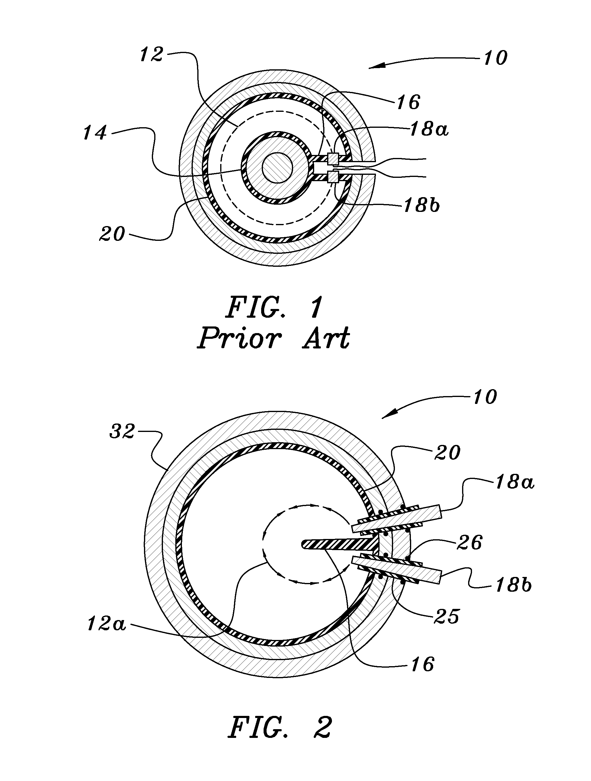
[0018]Turning now to FIG. 1 of the drawing, one finds a portion of a magnetic flow meter 10 having an extended, quasi-annular voltage sensing path 12, as described in the inventor's U.S. Pat. No. 6,571,642. As discussed above, the provision of an axial streamlined body 14 supported by a vane 16 defines a quasi-annular sensing path that is appreciably longer than is the corresponding path of a conventional magn...


PUM


Abstract

A magnetic flow meter has an electrically insulating member extending inward from an inner wall of a flow tube and extending along a selected axial portion of the tube. At least one pair of electrodes are placed adjacent opposite sides of the insulating member at a selected axial position so as to define a voltage sensing path. At least one of the electrodes is connected to an adjustment mechanism that allows the electrode to be set at a selected radial position, where the position can be selected so that the sensed voltage varies linearly with volumetric flow rate.

Description

BACKGROUND OF THE INVENTION[0001]1. Field of the Invention[0002]This invention relates to apparatus and method for determining the rate of flow of a fluid by measuring the electrical potential difference developed in the fluid as the fluid moves through a magnetic field.[0003]2. Background Information[0004]In many prior art in-line magnetic flow meters, an electrical potential difference developed in the fluid is generally sensed by a pair of electrodes contacting the liquid and spaced apart from each other by a voltage sensing path essentially equal to the diameter of a flow sensing passage. A magnetic field generated orthogonal to both the axis between the electrodes and the direction of flow through the sensing passage is provided by two coils of wire located on opposite sides of and outside of the passage.[0005]It is well known in the flow measurement arts that the velocity of a small volume of a fluid flowing in a pipe varies with the radial position of the small volume. The ma...

Claims


Application Information

Patent Timeline
IPC IPC(8): G01F1/58
CPCG01F1/584
Inventor FELLER, MURRAY F
Owner ONICON INC
Why Eureka
Try Eureka