
Ink jet printing apparatus and ink jet printing method

a printing apparatus and ink jet technology, applied in the direction of printing, other printing apparatus, etc., can solve the problems of easy appearance of stripe unevenness, difficult to manufacture stripe with no defect, and easy to increase manufacturing costs, so as to suppress uneven density and high quality printing

Inactive Publication Date: 2009-09-08
CANON KK
View PDF8 Cites 12 Cited by
  • Summary
  • Abstract
  • Description
  • Claims
  • Application Information

AI Technical Summary

Benefits of technology

[0017]The present invention provides an ink jet printing apparatus and an ink jet printing method which enable a high quality printing while suppressing uneven density in a conveying direction using a printing head having a plurality of ejection opening arrays.
[0021]According to the present invention, positional deviation of printing due to the distance between ejection openings is made inconspicuous so as to enable high quality printing to be achieved.

Problems solved by technology

Because of this, when the ejecting characteristic has a variation such that ejecting is not performed normally, and that an impact location displaces, this type has a defect that a fault in the picture such as stripe, stripe unevenness is easy of appearance.
Originally, it is to be desired that all ejection openings shall be manufactured with no defect and an excellent accuracy, however, the number of the ejection openings is great, therefore, it is very hard to manufacture them with no defect and the excellent accuracy.
For example, for performing the printing with the resolution of 1200 dpi in a sheet sized A3, it is necessary to provide about fourteen thousand units of the ejection openings (printing width 297 mm) in the printing head of the full line type, therefore, if they can be manufactured, manufacturing cost tends to increase because non-defective ratio is low.
However, the present inventors examined and revealed that, when the printing is performed using the printing head of the multi-array constitution like this, uneven density varied with respect to the main scanning direction, so called conveyance unevenness tends to occur.
Specifically, when the plural ejection opening arrays arranged in the main scanning direction are arranged mutually with a certain distance, it is found that the conveyance unevenness occurs remarkably as the distance between those ejection opening arrays becomes great.
This is caused by a phenomenon in which the printing medium may be conveyed meanderingly, at that time, there exists a difference of ejection timing between the ejection opening arrays, and as a result the impact location displaces, resulting in the uneven density.
In particular, in a photographic output in which high image quality is required, the uneven density like this becomes unacceptable level.
However, in this case, an effect of so called multi-array constitution, in which when a certain ejection opening has a failure of miss ejecting, other ejection opening performs supplemental ejecting, can not be obtained, therefore, the printing result with high quality printing can not be obtained.
Further, even when the meandering is generated in a part of the conveyance, it is evident that the above-mentioned problem is caused in that part.
However, the deviation generated on the apparatus like this is hard to be eliminated completely, therefore, the displacement of several 10 μm or so tends to be generated while conveying the printing medium.
However, the distance between the ejection opening arrays is hard to be shortened from a consideration of arrangement of the ejection opening, a wiring layout of the printing element provided in the ejection opening, securement of a space portion in which the ink jet printing head and a cap protecting the ink jet printing head may contact each other, and the like.

Method used


Image

  • Ink jet printing apparatus and ink jet printing method
  • Ink jet printing apparatus and ink jet printing method
  • Ink jet printing apparatus and ink jet printing method

Examples


first embodiment

[0038]Hereinafter, a first embodiment of the present invention will be described in detail with reference to drawings.

(Entire Configuration)

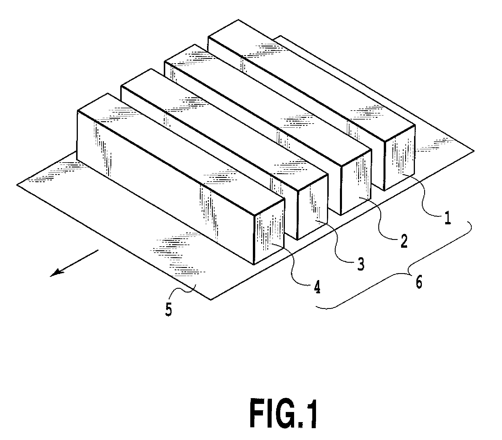
[0039]FIG. 1 is a perspective view showing a conceptual constitution of an ink jet printing apparatus relating to one embodiment of the present invention. A head unit 6 is constituted by a plurality of long printing heads 1, 2, 3, and 4, and a plurality of ejection openings equipped with printing elements therein (not shown) is provided in each of the printing heads 1, 2, 3, and 4. The plurality of ejection openings is arranged across the entire width of a printing region. The printing heads 1, 2, 3, and 4 are the long printing heads for ejecting inks of black (K), cyan (C), magenta (M), and yellow (Y), respectively. An ink supply tube not shown is connected to each of the printing heads 1, 2, 3, and 4, and furthermore, control signals and the like are sent through a flexible cable not shown.

[0040]A printing medium 5 such as plain paper or high ...

example

[0061]In this example, the printing head H1 was driven so that the ejecting amount of ink droplet from one ejection opening was 2.8 pl. Moreover, the drive frequency for ejecting ink droplet was set to 8 kHz and the printing resolution was set to 2400 dpi (main-scanning direction, conveying direction) X 2400 dpi (sub-scanning direction, ejection opening arrangement direction). Moreover, ink jet exclusive photo glossy paper (Pro Photopaper PR-101; manufactured by CANON Inc.) was prepared as the printing medium 5. Moreover, BCI-7 ink for a commercially available ink jet printer PIXUS iP7100 (manufactured by CANON Inc.) was used as ink. In addition, as test image data, patch image data including portions whose printing duty is 100%, 75%, 50%, and 25% were prepared. In addition, photographic image data including various duties other than the above-mentioned four duties was prepared.

[0062]The printing was performed under the condition as mentioned above. Specifically, binary ejection dat...

second embodiment

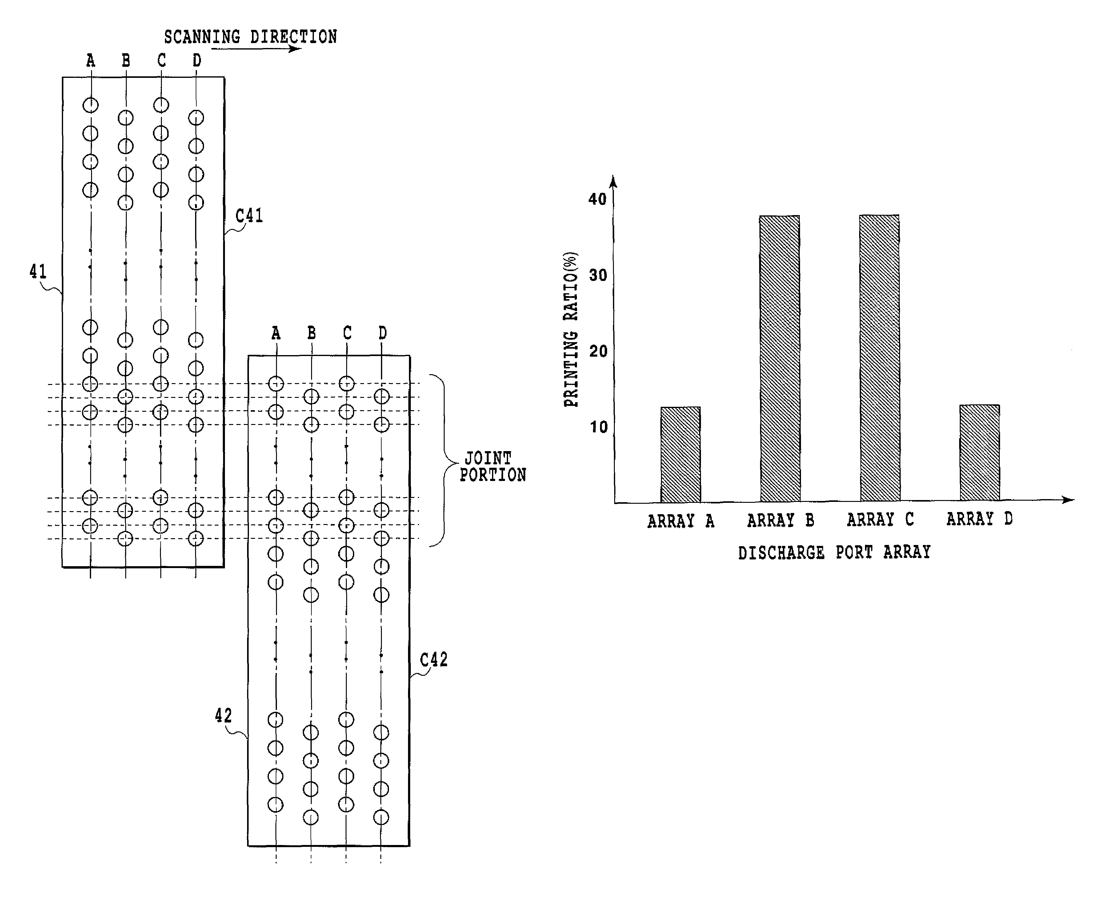
[0068]Like the first embodiment, the present embodiment makes the data assigning ratio for specific ejection opening arrays differ from that for other ejection opening arrays, but which array to be made to have a different data assigning ratio is different from the first embodiment. The present embodiment is similar to the first embodiment except the way of making the data assigning ratio different from each other.

[0069]In the present embodiment, like the first embodiment, the data assigning ratio for specific ejection opening arrays is made relatively higher and the data assigning ratio for ejection opening arrays other than the specific ejection opening arrays is made relatively lower. The difference between the present embodiment and the first embodiment is in the positions of specific ejection opening arrays and those of ejection opening arrays other than the specific ejection opening arrays. Namely, in the present embodiment, the specific ejection opening arrays are ejection op...


PUM


Abstract

An ink jet printing apparatus and an ink jet printing method are provided which use a printing head having a plurality of ejection opening arrays and enable high quality printing without causing uneven density in a conveying direction. For this purpose, by providing a plurality of ejection opening arrays to chips constituting the printing head and changing data assigning ratio of each ejection opening array, deviation in impact positions depending on the distance between the ejection opening arrays becomes inconspicuous.

Description

BACKGROUND OF THE INVENTION[0001]1. Field of the Invention[0002]The present invention relates to an ink jet printing apparatus and an ink jet printing method which perform printing by ejecting ink from a plurality of ejection openings to a printing medium. In detail, the present invention relates to an ink jet printing apparatus and an ink jet printing method which perform printing using a printing head equipped with a plurality of ejection opening arrays ejecting the same color ink.[0003]2. Description of the Related Art[0004]A printer or a copy machine and the like, or a printing apparatus used as an output device for composite electronics or a work station including a computer or a word processor is configured so that printing can be performed on a printing medium such as a paper or a plastic thin sheet based on printing information. The printing apparatus like this is classified into an ink jet type, a wire dot type, a thermal type, a laser beam type, or the like. The printing a...

Claims


Application Information

Patent Timeline
Patent Type & Authority Patents(United States)
IPC IPC(8): B41J2/15
CPCB41J2/2132
Inventor OCHIAI, TAKASHITSUBOI, HITOSHIWADA, SATOSHI
Owner CANON KK
Learn More