
Substrate processing apparatus

a processing apparatus and substrate technology, applied in the direction of photomechanical treatment, cleaning using liquids, instruments, etc., to achieve the effect of suppressing boun

Active Publication Date: 2009-09-08
DAINIPPON SCREEN MTG CO LTD
View PDF28 Cites 29 Cited by
  • Summary
  • Abstract
  • Description
  • Claims
  • Application Information

AI Technical Summary

Benefits of technology

The present invention is a substrate processing apparatus that can suppress the splashing of a processing liquid flying spattering from a substrate in rotation. The apparatus includes a substrate holding part, a rotary part, a processing liquid supply part, a plurality of guide parts, and a position adjusting part. The guide parts trap the processing liquid flying spattering from the substrate in rotation. The apparatus also includes a recovery system to recover the processing liquid flying spattering from the substrate. The recovery system includes a plurality of recovery tanks and pipes to connect the recovery tanks to the substrate holding part. The apparatus reduces the time that the processing liquid is present in the recovery tank and prevents contamination of the substrate. The invention also includes a splash guard to prevent processing liquid flying spattering from the substrate. The technical effects of the invention are to suppress the splashing of processing liquid flying spattering from the substrate and improve the efficiency of substrate processing.

Problems solved by technology

This causes the problem that the peripheral part of the substrate held by the spin base is considerably close to the upper part of the innermost cup and the processing liquid flying spattering from the substrate in rotation strikes the cups and it becomes fine droplets to be attached on the substrate surface.
There is also the possibility that the processing liquid so adhered to the substrate is then dried to form particles contaminating the substrate.

Method used


Image

  • Substrate processing apparatus
  • Substrate processing apparatus
  • Substrate processing apparatus

Examples


Embodiment Construction

[0039]Preferred embodiments of the present invention will be described in detail by referring to the accompanying drawings.

1. First Preferred Embodiment

1-1. Configuration of Substrate Processing Apparatus

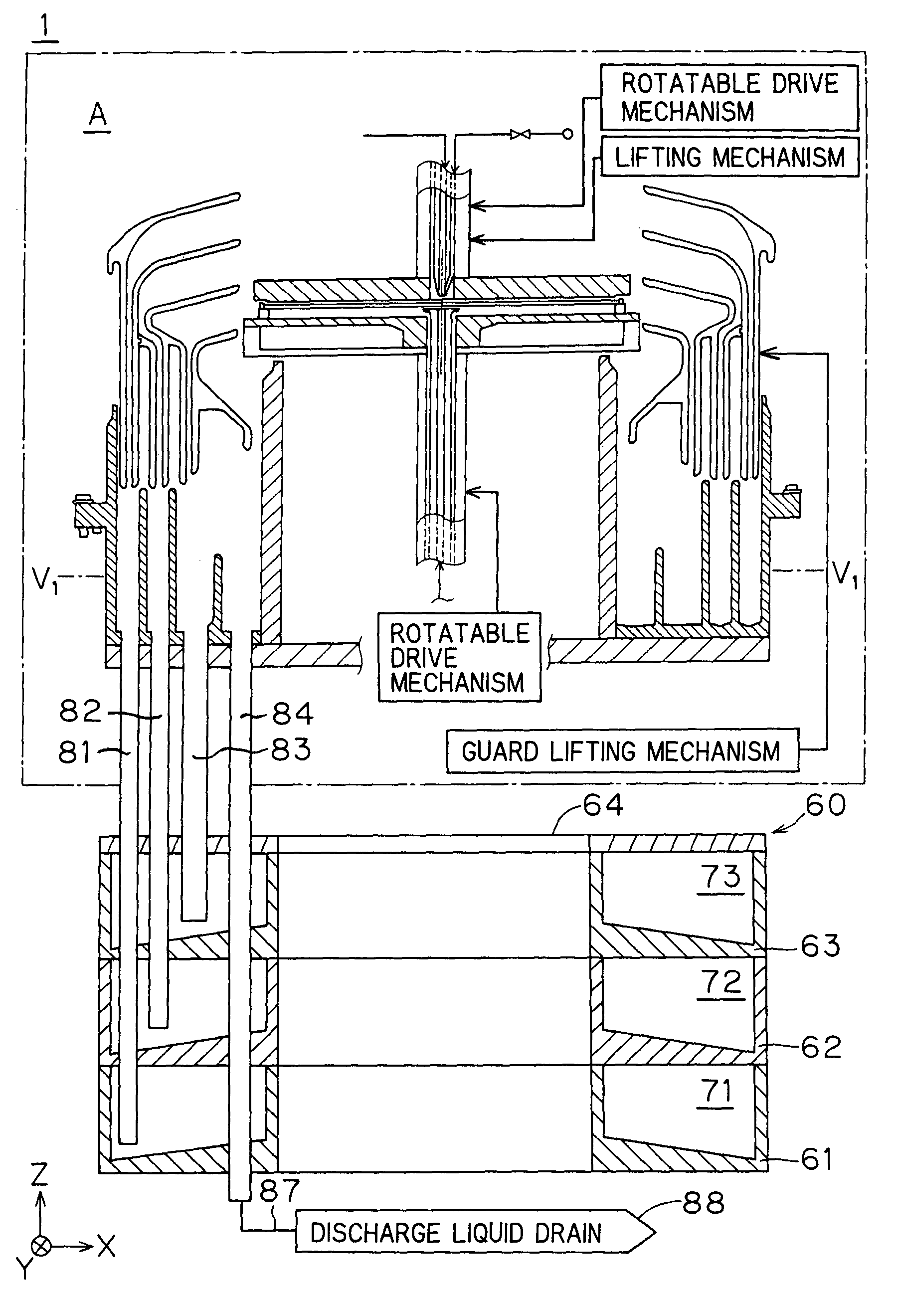
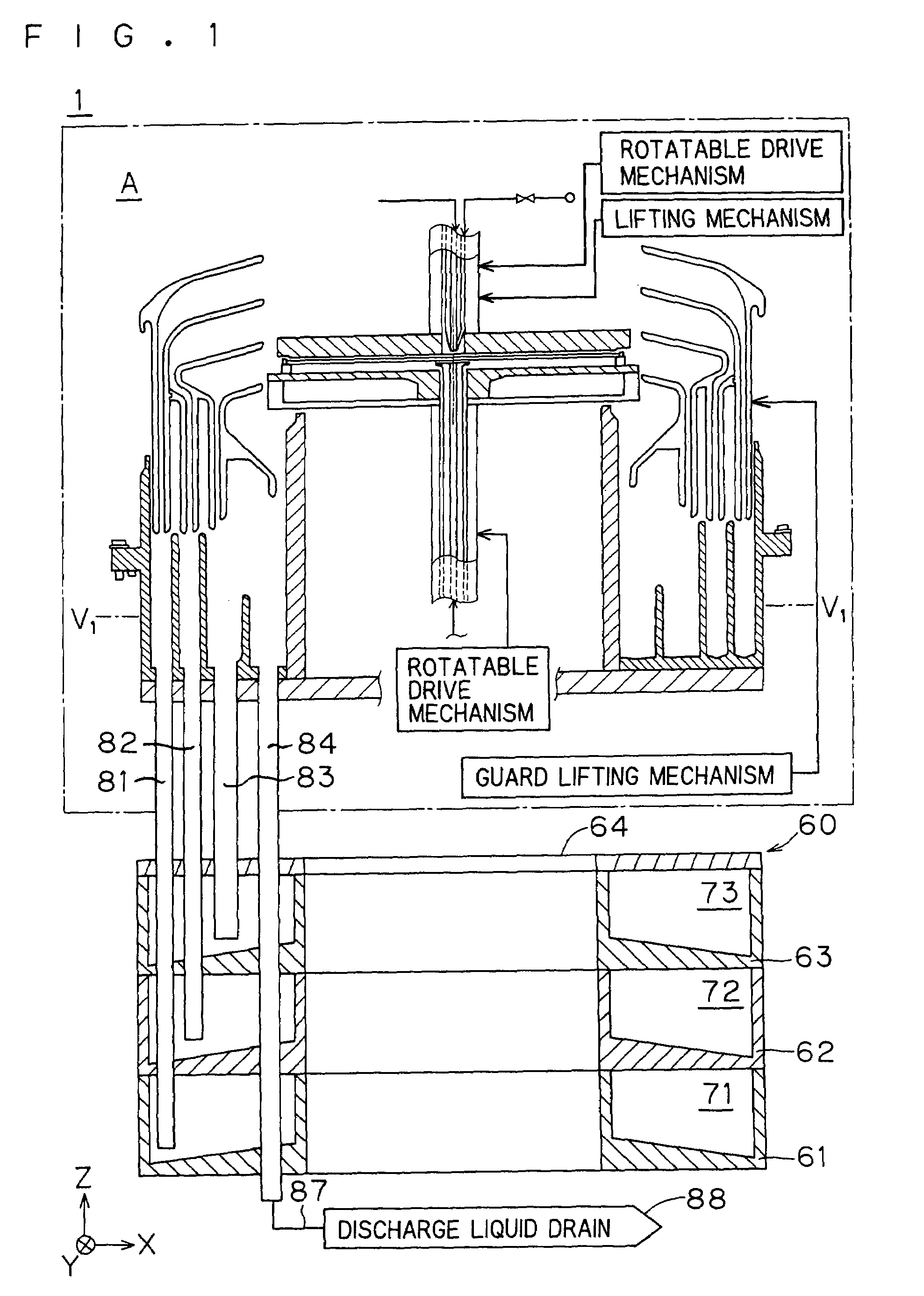
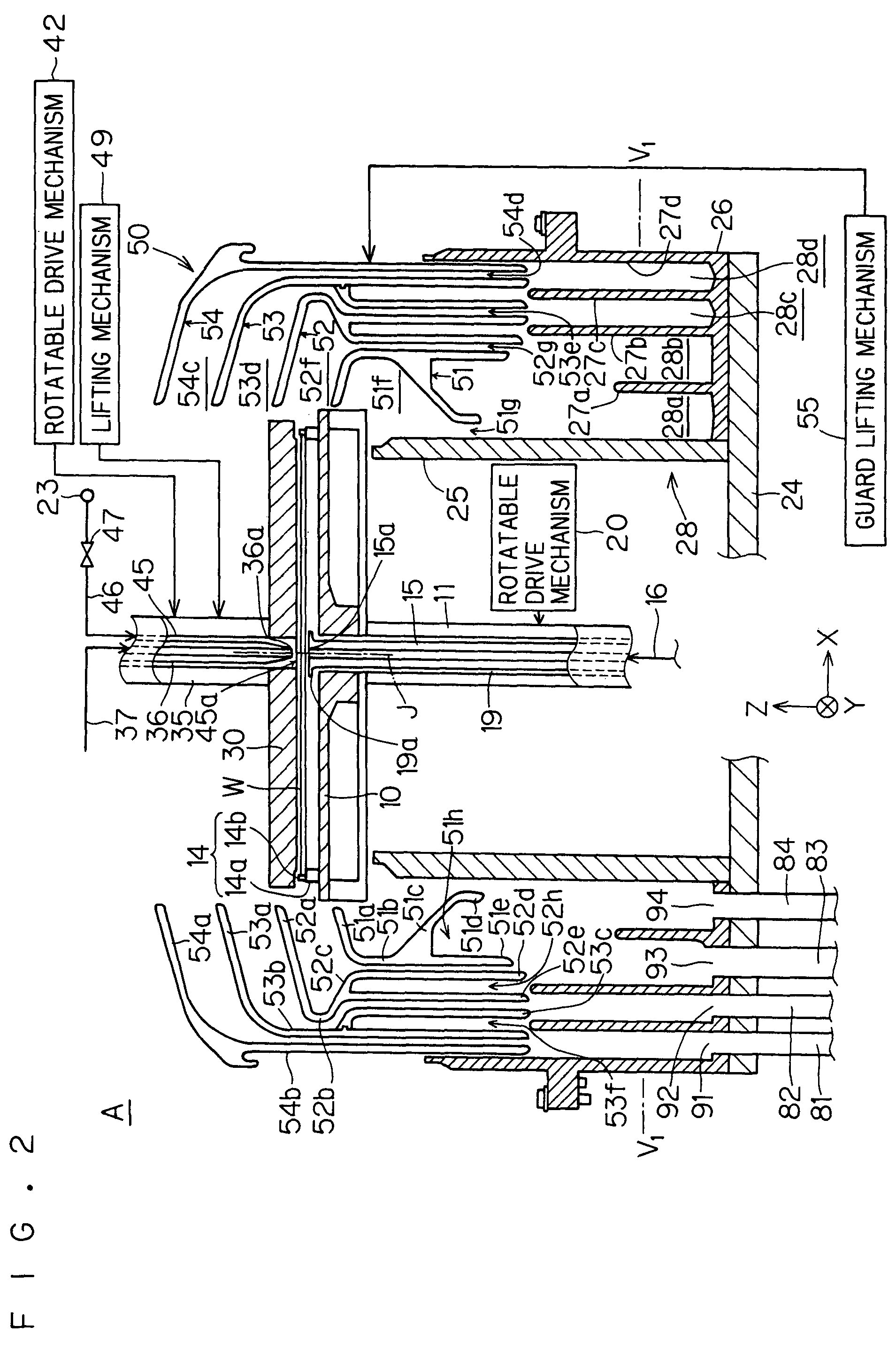
[0040]FIG. 1 is a longitudinal sectional view of the configuration of a substrate processing apparatus 1 of the present invention. FIG. 2 is a diagram showing in enlarged dimension section ‘A’ (the range surrounded by dash-single-dot line) of the substrate processing apparatus 1 of FIG. 1. FIG. 3 is a diagram showing one example of a supply part that supplies a processing liquid and inert gas to a substrate. FIG. 4 is a diagram showing a cross section in the vicinity of a discharged liquid tank (recovery tank), which will be described hereinafter.

[0041]The substrate processing apparatus 1 of the first preferred embodiment is capable of performing processes such as bevel etching by supplying a chemical solution to a lower surface of a substrate W that is a semiconductor wafer. In FIG...


PUM

PropertyMeasurementUnit
timeaaaaaaaaaa
timeaaaaaaaaaa
timeaaaaaaaaaa

Abstract

A substrate (W) is held and rotated in its horizontal position on a spin base (10). A processing liquid can be supplied from a processing liquid lower nozzle 15 to the lower surface of the substrate (W). The upper surface of the substrate (W) is covered with an atmosphere blocking plate (30). A splash guard (50) is disposed so as to circumscribe the substrate (W). A guard (52) is curved such that the vertical cross section of a recovery port (52f) of the splash guard (50) is of substantially U-shape opening to the center of the splash guard (50), so that the maximum internal diameter part of the recovery port (52f) is brought near a guard (53). The space between the internal wall surface of the recovery port (52f) and the substrate (W) is increased to thereby suppress the bounce of the processing liquid flying spattering from the substrate (W) in rotation.

Description

BACKGROUND OF THE INVENTION[0001]1. Field of the Invention[0002]The present invention relates to a substrate processing apparatus that performs a predetermined substrate process such as cleaning process by supplying a processing liquid to a semiconductor substrate, glass substrate for liquid crystal display, glass substrate for photomask, substrate for optical disk or the like (hereinafter referred to simply as a “substrate”), while rotating the substrate.[0003]2. Description of the Background Art[0004]There has conventionally been used a substrate processing apparatus of single-wafer type that performs etching and cleaning processes by supping a chemical solution or rinsing pure water (chemical solution and pure water are generally called “processing liquid” in the present specification) to the surface and / or reverse of a substrate mounted on a spin base, while rotating the substrate. The substrate processing apparatus of this type is usually provided with a cup unit for receiving ...

Claims


Application Information

Patent Timeline
Patent Type & Authority Patents(United States)
IPC IPC(8): B08B3/00B08B17/00G03F1/82H01L21/00H01L21/687
CPCB08B17/00H01L21/68792H01L21/6708H01L21/68785H01L21/67051G03F1/82Y10S134/902
Inventor MIYA, KATSUHIKOIZUMI, AKIRAKAWAMURA, TAKASHIKAJINO, ITSUKI
Owner DAINIPPON SCREEN MTG CO LTD
Learn More