
Signal-detect-based ranging technique for burst-mode optical systems

a technology of optical systems and signal detection, applied in time-division optical multiplex systems, multi-component communication, electromagnetic transmission, etc., can solve problems such as bit errors, active components are subject to failure and performance degradation, and require significant periodic maintenance, so as to minimize the probability of receiver production and minimize the length of time

Active Publication Date: 2009-09-01
ALCATEL LUCENT SAS
View PDF2 Cites 30 Cited by
  • Summary
  • Abstract
  • Description
  • Claims
  • Application Information

AI Technical Summary

Benefits of technology

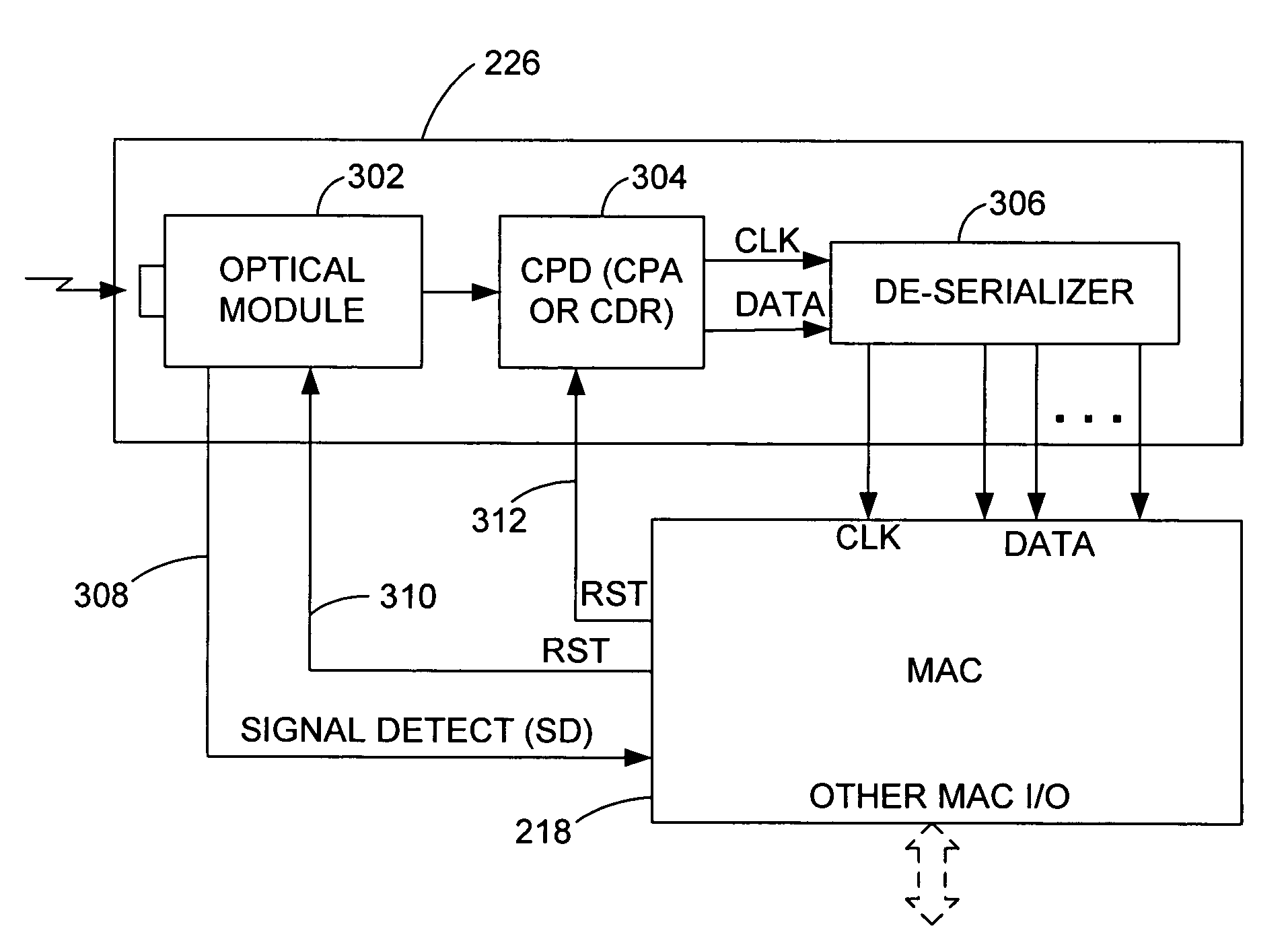
[0014]Asserting burst-mode receiver reset signals when the presence of a packet signal (i.e., light) is first detected minimizes the length of time that a signal is absent from the receiver input before the arrival of actual packet data and thereby minimizes the probability that the receiver will produce a spurious output.

Problems solved by technology

In addition to requiring power, active components are subject to failure and performance degradation over time, and may require significant periodic maintenance.
Bit errors can occur if the OLT receiver threshold is too high or too low to detect the bits of a packet.
Nevertheless, because some ONUs may be located at different distances from the OLT than other ONUs, differences in propagation delays may cause data packet transmissions to overlap slightly in time and become garbled with each other at splitters / combiners.
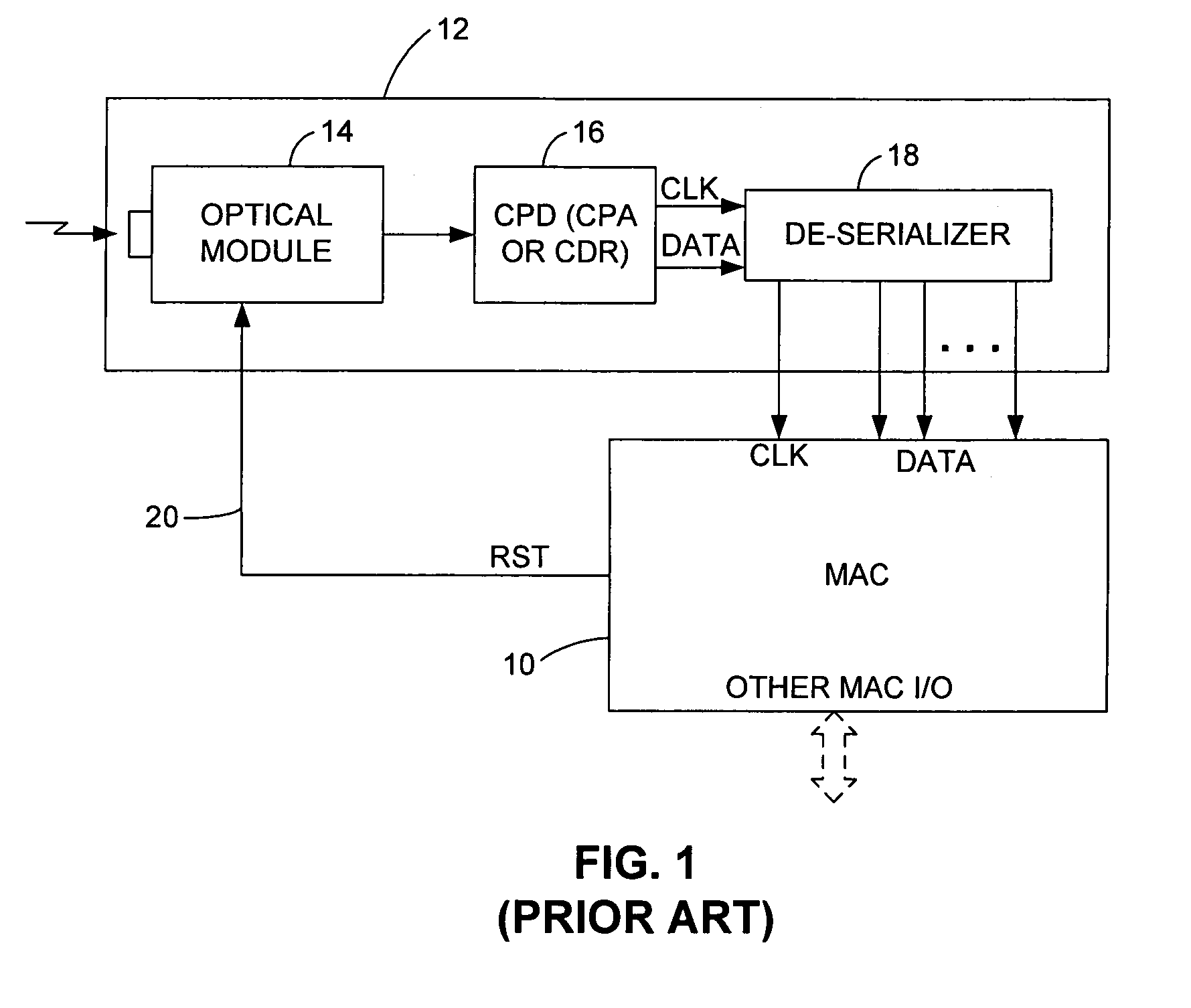
A problem arises, however, when the packet is not an ordinary data packet, but rather a ranging reply, because MAC 12 cannot determine when a ranging reply will be received.
In the high-gain mode, optical module 14 is unduly sensitive to noise spikes and is thus very susceptible to producing spurious bit outputs.
Although not all burst-mode optical receiver architectures necessarily behave in this manner with regard to entering a high-gain mode, essentially all such receivers suffer from the problem that the longer an input (light) signal is absent, the higher the probability that the receiver will produce a spurious output, which will almost always cause the MAC to produce errors.
Determining the optimal condition or conditions under which to assert such a reset signal during ranging has been problematic in the art.

Method used


Image

  • Signal-detect-based ranging technique for burst-mode optical systems
  • Signal-detect-based ranging technique for burst-mode optical systems
  • Signal-detect-based ranging technique for burst-mode optical systems

Examples


Embodiment Construction

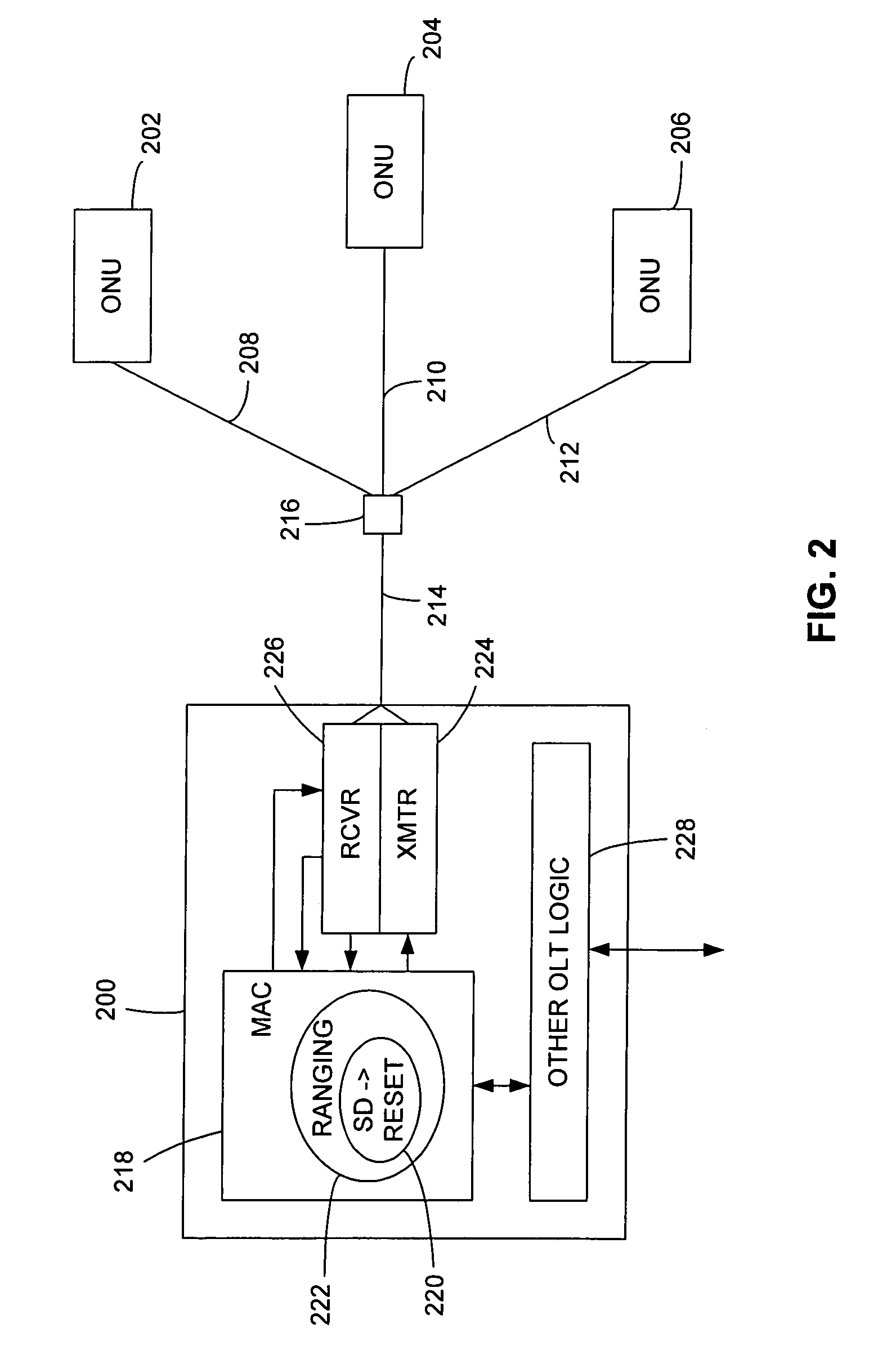
[0020]As illustrated in FIG. 2, in an exemplary embodiment of the present invention a passive optical network (PON) includes an optical line terminator (OLT) 200 and a number of optical network units (ONUs) 202, 204, 206, etc. The OLT 200 is interconnected in the conventional manner with each ONU 202, 204, 206, etc., by optical fibers 208, 210, 212, 214, etc., and one or more optical splitters 216, etc. Although only one such splitter 216 and three such ONUs 202, 204 and 206 are shown for purposes of illustration, the PON can have any other suitable topology and number of ONUs, splitters, fibers, etc. The OLT 200 can be located at, for example, an exchange or central office from which services are provided, such as distribution of television programming and provision of Internet access. The ONUs 202, 204, 206, etc., can be located at, for example, residences or other premises occupied by subscribers to such services. Although data communication in the PON is bidirectional, the prese...


PUM


Abstract

In a passive optical network (PON), a burst-mode receiver of an optical line terminator (OLT) is initialized during an initialization phase, such as ranging, by asserting one or more reset signals in response to detecting the presence of a packet signal. For example, after the OLT transmits an initialization message, such as a ranging grant, to an optical network unit (ONU), it asserts one or more reset signals when it detects the presence of a packet signal received from the ONU in response.

Description

BACKGROUND OF THE INVENTION[0001]1. Field of the Invention[0002]The present invention relates generally to data transmission in a passive optical network (PON) and, more specifically, to an improvement in the ranging process that is performed prior to initiating (time-division multiplexed) upstream transmissions.[0003]2. Description of the Related Art[0004]Most digital telecommunications networks (i.e., networks that facilitate the communication of data, voice, video, etc., between parties or between a content distribution service and subscribers) typically comprise active components, such as repeaters, relays and other such devices that consume power, in the path between an exchange and a subscriber. In addition to requiring power, active components are subject to failure and performance degradation over time, and may require significant periodic maintenance. The passive optical network (PON) has been developed to overcome some of these deficiencies. The essence of a PON is that no...

Claims


Application Information

Patent Timeline
Patent Type & Authority Patents(United States)
IPC IPC(8): H04J14/08
CPCH04J3/0682H04J3/1694H04J2203/0067
Inventor DALTON, RODGERRUEGG, EUGEN H.TEETER, JASON
Owner ALCATEL LUCENT SAS
Learn More