Power supply device and image forming apparatus using the power supply device
a technology of power supply device and power supply device, which is applied in the direction of generator/motor, electrographic process, instruments, etc., can solve the problems of long rise time of high voltage output, delay of sweep time of frequency, and difficulty in reducing the size and weight of the whole apparatus, so as to shorten the rise time of high voltage
- Summary
- Abstract
- Description
- Claims
- Application Information
AI Technical Summary
Benefits of technology
Problems solved by technology
Method used
Image
Examples
first exemplary embodiment
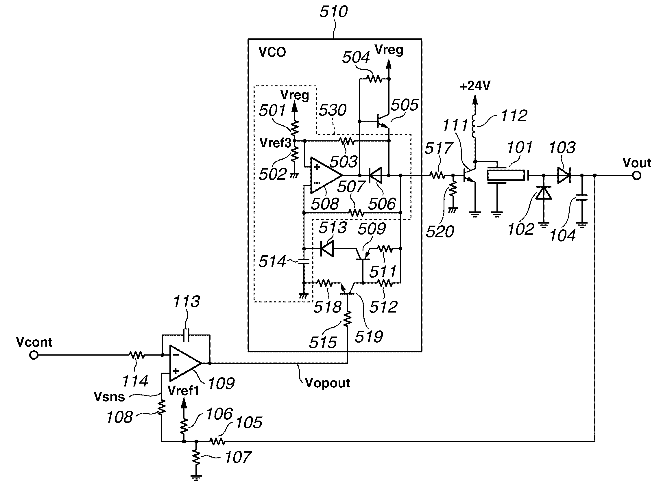
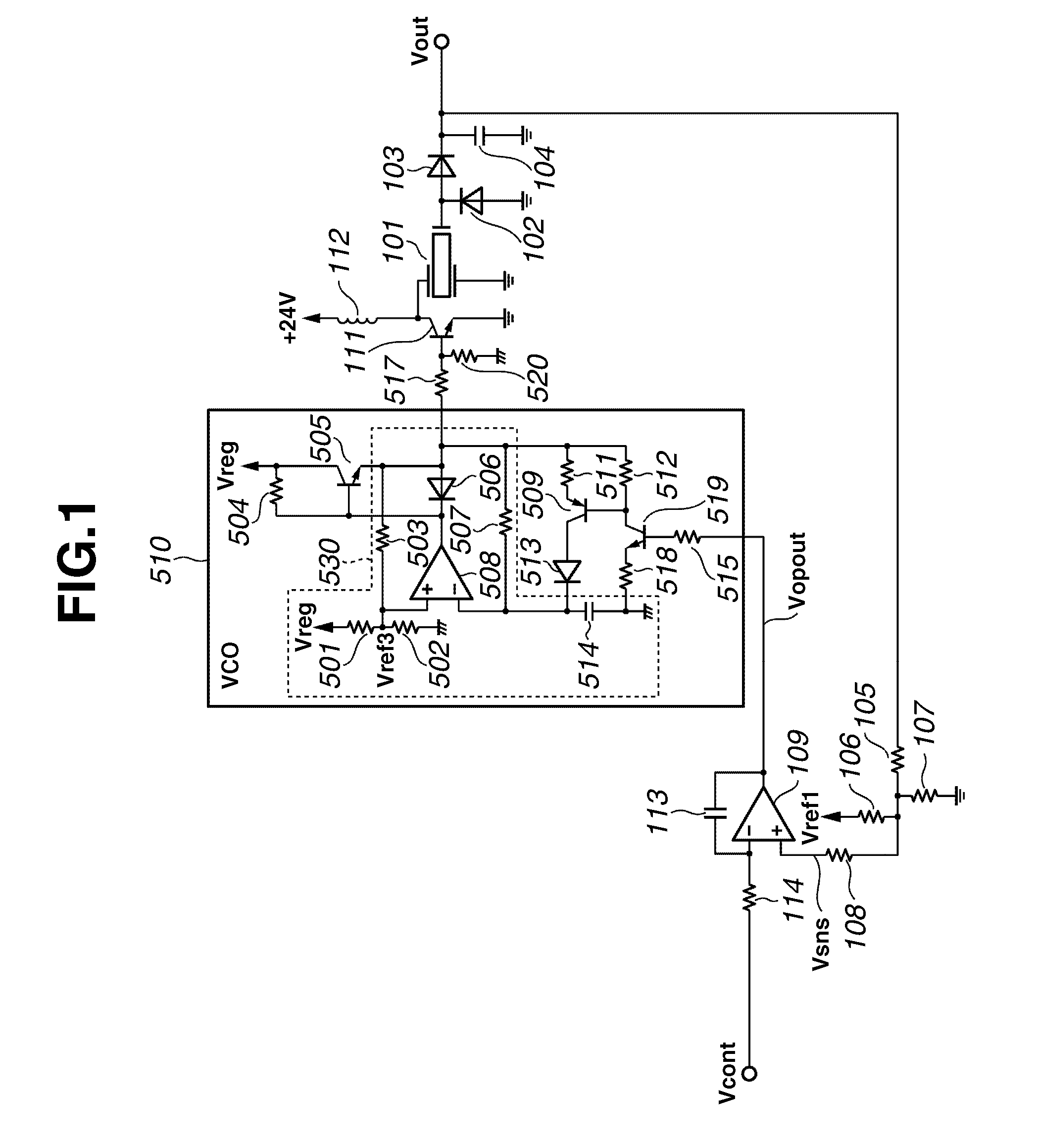
[0043]FIG. 1 is a diagram showing a high voltage power supply circuit of the piezoelectric transformer type employed in the high voltage power supply unit 202 according to a first exemplary embodiment of the present invention. In FIG. 1, Reference numeral 101 denotes the piezoelectric transformer (piezoelectric ceramic transformer), Reference numerals 102, 103, 506, and 513 denote diodes, and Reference numerals 104, 113, and 514 denote capacitors. Reference numerals 105-108, 114, 501-504, 507, 511, 512, 515, 517, 518, and 520 denote resistors, Reference numeral 109 denotes an operational amplifier, and Reference numerals 111, 505, 509, and 519 denote transistors. Reference numeral 112 denotes an inductor, Reference numeral 508 denotes a comparator, Reference numeral 510 denotes a voltage controlled oscillator (VCO), and Reference numeral 530 denotes a CR oscillating circuit.
[0044]Output of the piezoelectric transformer 101 is rectified and smoothed to the positive voltage by the dio...
second exemplary embodiment
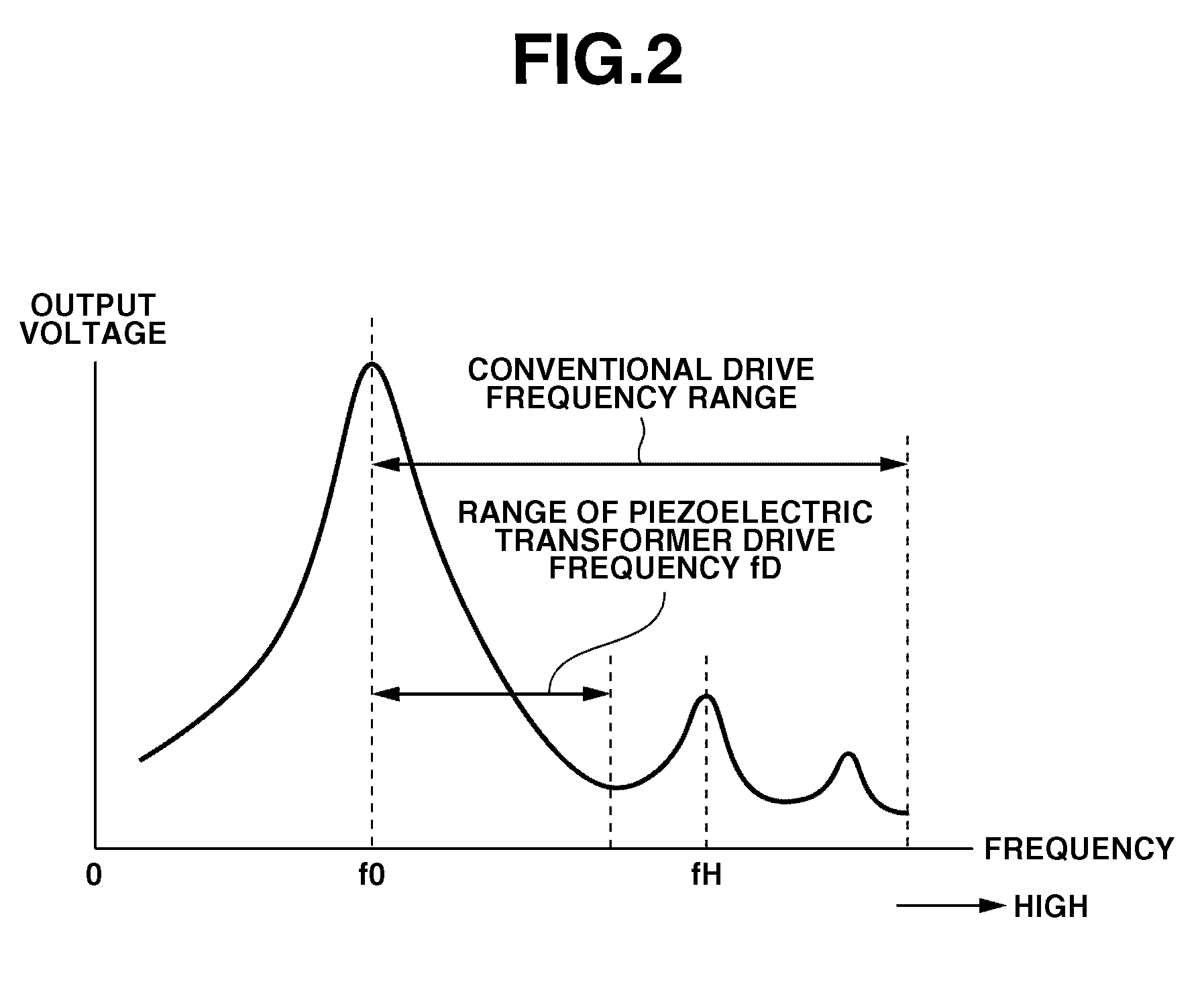
[0056]A main difference of the second exemplary embodiment from the first exemplary embodiment is to set the range of the drive frequency fD of the piezoelectric transformer 101 to be on the frequency side that is lower than the resonant frequency f0 of the piezoelectric ceramic vibration body.
[0057]FIG. 4 is a diagram showing a high voltage power supply circuit of the piezoelectric transformer type according to the second exemplary embodiment of the present invention.
[0058]The circuit illustrated in FIG. 4 includes a push-pull circuit configured by transistors 505 and 521 without using the transistor 111 and inductor 112 in FIG. 1 of the first exemplary embodiment. The piezoelectric transformer is pulse-driven directly by a source voltage via a resistor 522.
[0059]According to the second exemplary embodiment, the piezoelectric transformer 101 is driven in the frequency range on the lower frequency side of the resonant frequency f0. In contrast to the VCO 510 according to the first e...
third exemplary embodiment
[0066]According to the first or second exemplary embodiment, the piezoelectric transformer 101 operates even if the control signal Vcont is 0 V, and a micro output voltage Vcont is maintained. Therefore, the output voltage Vout will not become completely 0 V. Consequently, a voltage is always applied to process members such as photoreceptors and transfer rollers of an electrophotographic printer. This state shortens a life of process members. It is also a problem that power is uselessly consumed due to a continuous operation of the piezoelectric transformer 101.
[0067]Thus, in the configurations described in the first or second exemplary embodiment, the output voltage Vout is set completely to 0 V according to the third exemplary embodiment when the output voltage Vout falls to a prescribed voltage below the output voltage used for image forming operations.
[0068]The third exemplary embodiment is applicable to both configurations in which the piezoelectric transformer 101 is controlle...
PUM
 Abstract
Description
Claims
Application Information
 - R&D
- Intellectual Property
- Life Sciences
- Materials
- Tech Scout
- Unparalleled Data Quality
- Higher Quality Content
- 60% Fewer Hallucinations
Browse by: Latest US Patents, China's latest patents, Technical Efficacy Thesaurus, Application Domain, Technology Topic, Popular Technical Reports.
© 2025 PatSnap. All rights reserved.Legal|Privacy policy|Modern Slavery Act Transparency Statement|Sitemap|About US| Contact US: help@patsnap.com


