
Minimally invasive medical device deployment and retrieval system

a medical device and minimally invasive technology, applied in the field of minimally invasive surgical procedures, can solve the problems of affecting the effect reducing the efficiency of the surgical procedure, so as to achieve the effect of effectively trapping any emboli or other materials

Inactive Publication Date: 2009-08-25
EV3
View PDF29 Cites 105 Cited by
  • Summary
  • Abstract
  • Description
  • Claims
  • Application Information

AI Technical Summary

Benefits of technology

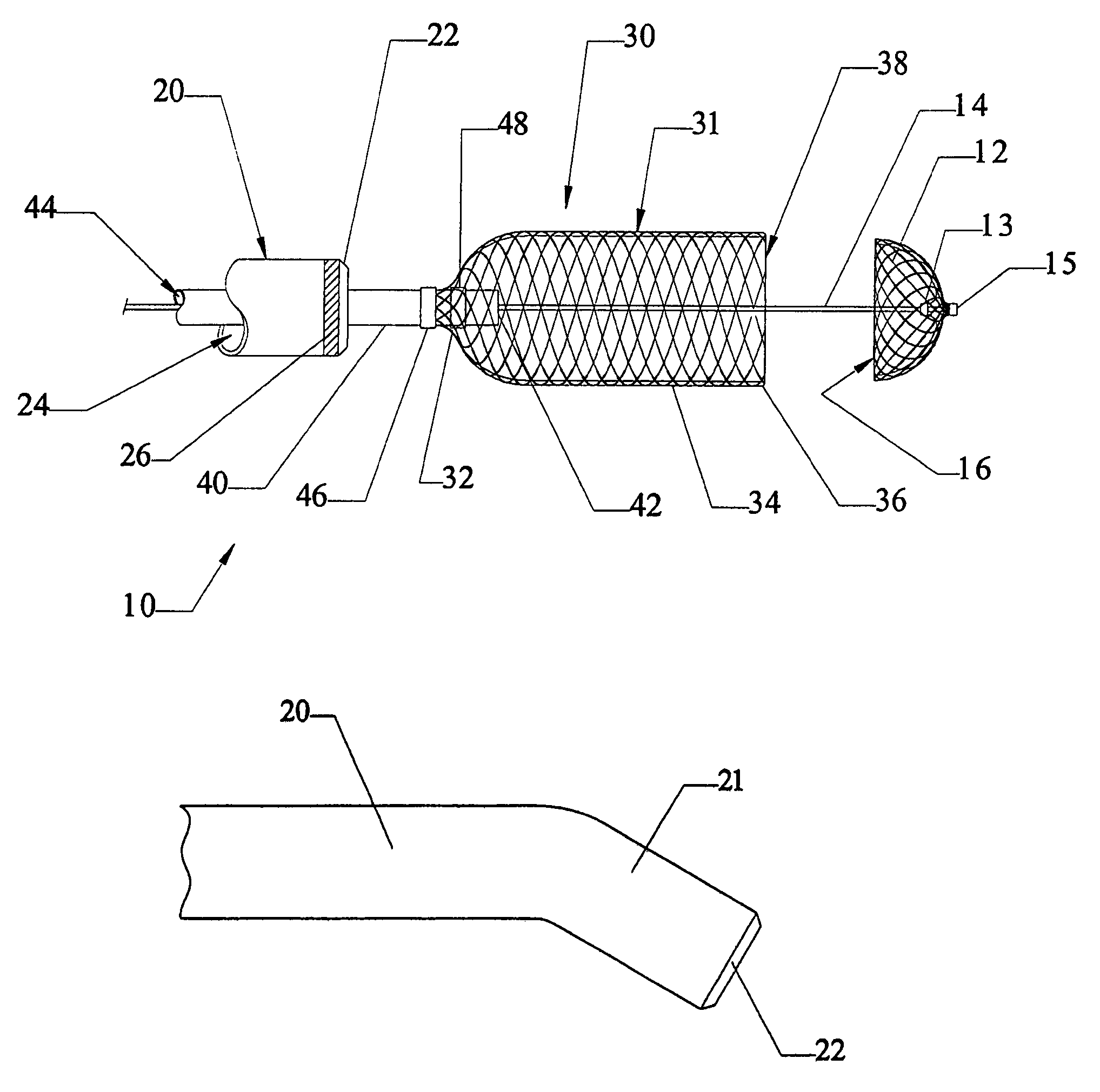
[0048]Another embodiment of the invention provides a retractable medical device system including a medical device, a retrieval cover and a retrieval sheath. The medical device comprises a working element carried by a flexible, elongate shaft. The retrieval cover is slidable along the shaft of the medical device. The cover has a radially reduced proximal portion, a distally open distal end an elongate tubular wall extending therebetween and defining a recess. The working element of the medical device is completely retained within the recess of the cover such that the tubular wall extends distally beyond the medical device. The retrieval sheath has a lumen and is slidable with respect to both the medical device and the cover. At least a proximal length of the working element of the medical device and the cover are retained within the lumen of the retrieval sheath, with the retrieval sheath regularly compressing the proximal length of the cover such that an intermediate portion of the wall tightly engages the surface of the medical device. This will tend to effectively trap any emboli or other materials retained by the medical device.

Problems solved by technology

In the course of improving the patency of the blood vessel utilizing these techniques, there is a risk that the material which was formally causing the obstruction within the vessel can simply float downstream with the flow of blood to the vessel.
Unfortunately, many designs of such temporary filters may get relatively difficult or complex to retract the trap back in to the catheter through which it was delivered without simply dumping the trapped thrombi back in to the bloodstream.
This can tend to be relatively cumbersome, though, and may be too difficult to effectively accomplish without breaking the tethers if the device is deployed at a selective site reached by a tortuous path, such as in the brain.
This will tend to cause the cover to collapse about the basket, tightly engaging the outer surface of the basket.
When the stenosis is treated in this fashion, though, there is a risk that some debris will break free and enter the blood flowing through the vessel.
If left unchecked, this embolus can drift downstream and embolize a distal portion of the vessel.
Depending on where the embolus comes to rest, the embolization can result in significant tissue or organ damage.

Method used


Image

  • Minimally invasive medical device deployment and retrieval system
  • Minimally invasive medical device deployment and retrieval system
  • Minimally invasive medical device deployment and retrieval system

Examples


Embodiment Construction

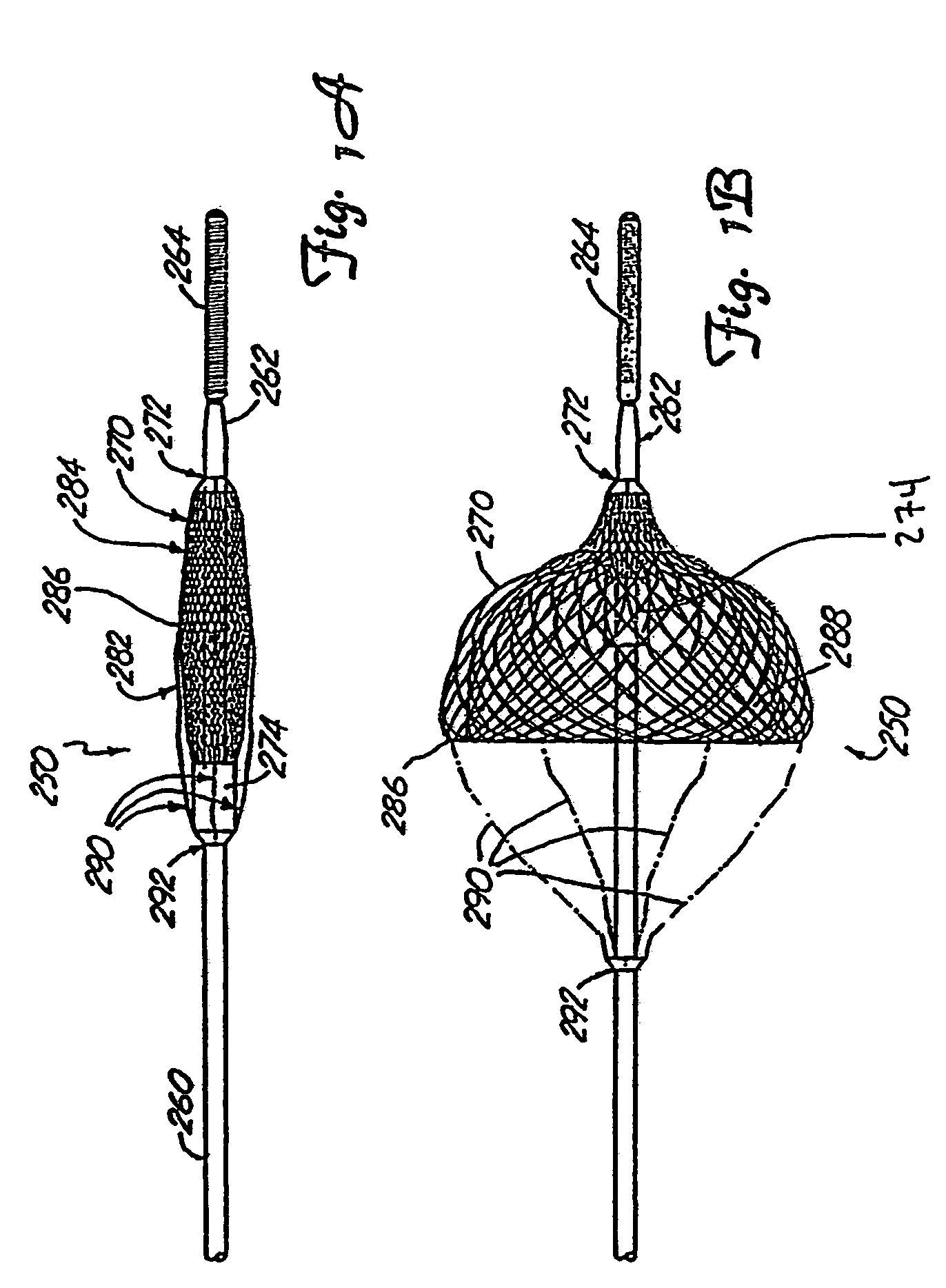
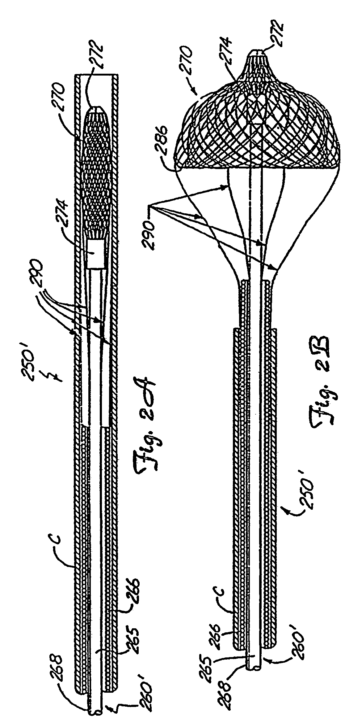
[0066]FIGS. 8-12 schematically illustrate the operation of one embodiment of the present invention. FIG. 8 illustrates certain operative portions of the medical device retrieval system 10 of the invention in a fully deployed state. As noted above, the retrieval system of the invention is intended to be used in connection with a medical device having a working element carried by flexible, elongate shaft. In these drawings, the medical device is typified as a vascular trap similar to the vascular trap 250 of FIG. 11, but omitting the tethers 290. The working element of this medical device is a basket 12, which may be substantially as outlined above in connection with the description of the basket 270. The shaft in this design may simply comprise a guidewire 14. While the construction and operation of the basket 12 may be substantially the same as that outline for the baskets shown in FIGS. 1-5, it is generally preferred that the proximal band 13 of this basket be attached to the guide...


PUM


Abstract

The present invention provides a medical device retrieval system comprising a working element carried by a flexible, elongate shaft, the working element having a proximal profile and the shaft extending proximally from the working element and a retrieval cover slidable carried along the shaft of the medical device, the cover having a deployed configuration and being capable of being compressed into a compressed configuration for deployment, yet resiliently substantially return to the deployed configuration; the cover in its deployed configuration having a radially reduced proximal portion, a distally open distal end defining a distal opening having a maximum dimension at least as great as the maximum dimension of the proximal profile of the working element of the medical device, and an elongate internal recess defined between the proximal portion and the distal end.

Description

CROSS REFERENCE TO RELATED APPLICATION[0001]The present application is a continuation of application Ser. No. 10 / 184,327, filed Jun. 27, 2002 now abandoned, which is a continuation of prior application Ser. No. 09 / 936,248, filed Jan. 28, 2002 now abandoned as a national stage filing under 35 U.S.C. § 371 of International Application No. PCT / US00 / 06212, filed on Mar. 8, 2000, which claims the priority date of provisional patent application U.S. Ser. No. 60 / 124,156, filed Mar. 8, 1999. Internatonal Application No. PCT / US00 / 06212 was published as WO 00 / 53120 on Sep. 14, 2000. The full disclosures of application Ser. No. 10 / 184,327, application Ser. No. 09 / 936,248, International Application No. PCT / US00 / 06212 and U.S. Ser. No. 60 / 124,156 are incorporated herein by reference.FIELD OF THE INVENTION[0002]The present invention generally relates to minimally invasive surgical procedures, e.g., angioplasty and atherectomy procedures, and has particular utility in connection with retrieving a ...

Claims


Application Information

Patent Timeline
Patent Type & Authority Patents(United States)
IPC IPC(8): A61M29/00A61F2/01
CPCA61F2/013A61F2002/011A61F2230/0069A61F2230/0006A61F2230/0093A61F2002/018A61F2230/008A61B17/221A61F2/011
Inventor KUSLEIKA, RICHARD S.NGUYEN, DUYANDERSON, KENT D.
Owner EV3
Learn More