
Method of programming a lighting preset from a radio-frequency remote control

a radio frequency remote control and preset technology, applied in the direction of electric variable regulation, process and machine control, instruments, etc., can solve the problems of confusing the sequence of events of users, lighting control systems can only transmit a limited number of rf signals, and the fcc limitations of intentional power transmitted

Active Publication Date: 2009-08-11
LUTRON TECH CO LLC
View PDF33 Cites 292 Cited by
  • Summary
  • Abstract
  • Description
  • Claims
  • Application Information

AI Technical Summary

Benefits of technology

"The present invention provides a method for programming a load control device to control the amount of power delivered to a lighting load to a specific intensity. The method involves controlling the intensity of the lighting load to an old preset intensity in response to receiving a wireless transmission, providing a visual indication representative of the new intensity in response to receiving a first predetermined number of wireless transmissions with no more than a first predetermined time period between two consecutive wireless transmissions, and storing the new intensity as the preset intensity in response to receiving a second predetermined number of wireless transmissions with no more than a second predetermined time period between two consecutive wireless transmissions. The invention also provides a dimmer switch for controlling the intensity of a lighting load to a new intensity and a lighting control system for controlling the intensity of a lighting load to a preset intensity."

Problems solved by technology

FCC limitations on average intentional power transmitted.
However, periodic transmissions are acceptable as long as the FCC limitations on the average intentional power transmitted are observed.
As a consequence of complying with the FCC regulations, RF lighting control systems can only transmit a limited number of RF signals in a given time period.
Because of the limitations on how often a control device of an RF lighting control system can transmit RF signals, an RF control device receiving an RF signal must respond rather quickly to the received RF signal, for example, after receiving only one or two RF signals.
This sequence of events can be confusing to a user.

Method used


Image

  • Method of programming a lighting preset from a radio-frequency remote control
  • Method of programming a lighting preset from a radio-frequency remote control
  • Method of programming a lighting preset from a radio-frequency remote control

Examples


Embodiment Construction

[0023]The foregoing summary, as well as the following detailed description of the preferred embodiments, is better understood when read in conjunction with the appended drawings. For the purposes of illustrating the invention, there is shown in the drawings an embodiment that is presently preferred, in which like numerals represent similar parts throughout the several views of the drawings, it being understood, however, that the invention is not limited to the specific methods and instrumentalities disclosed.

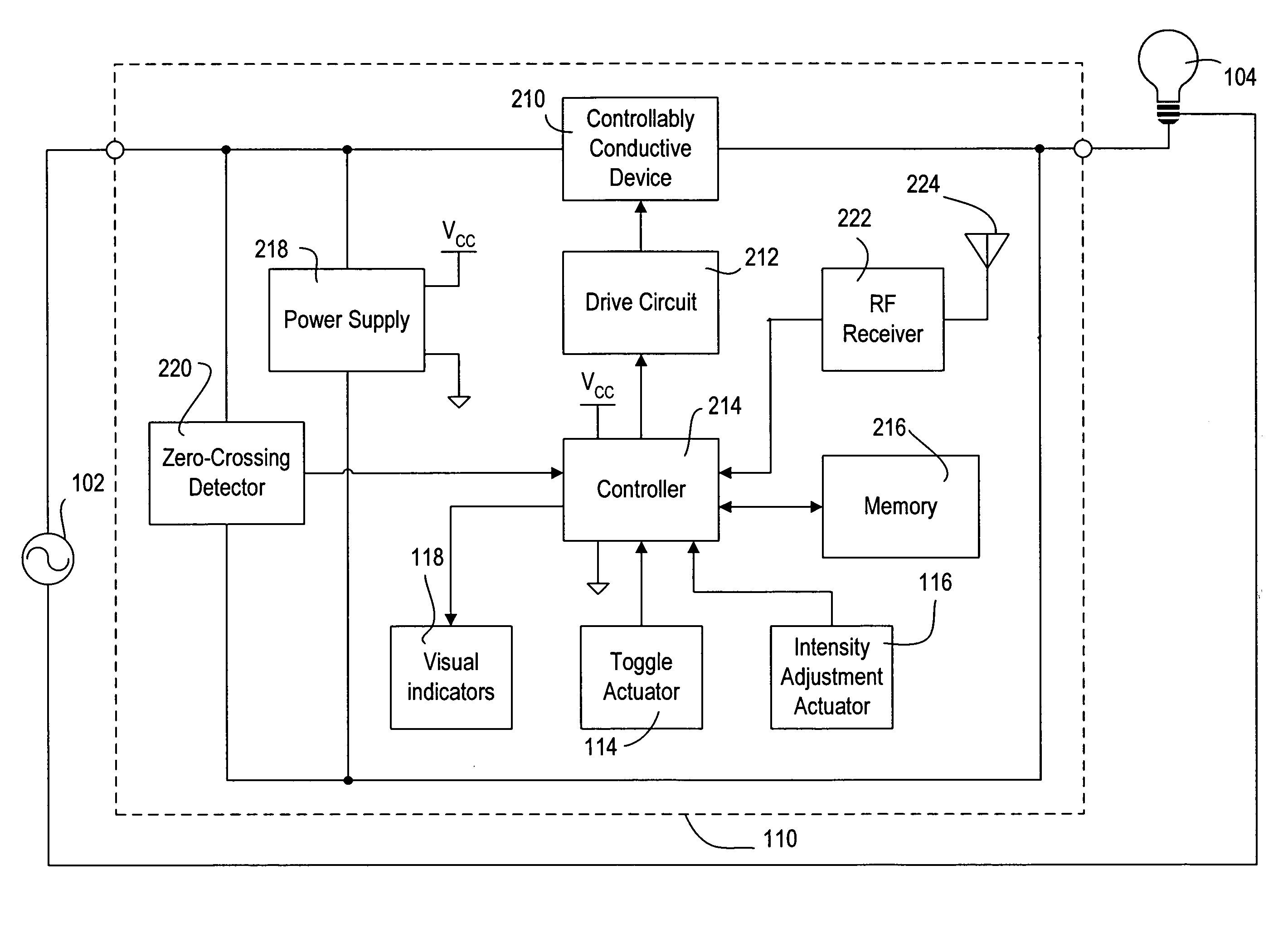
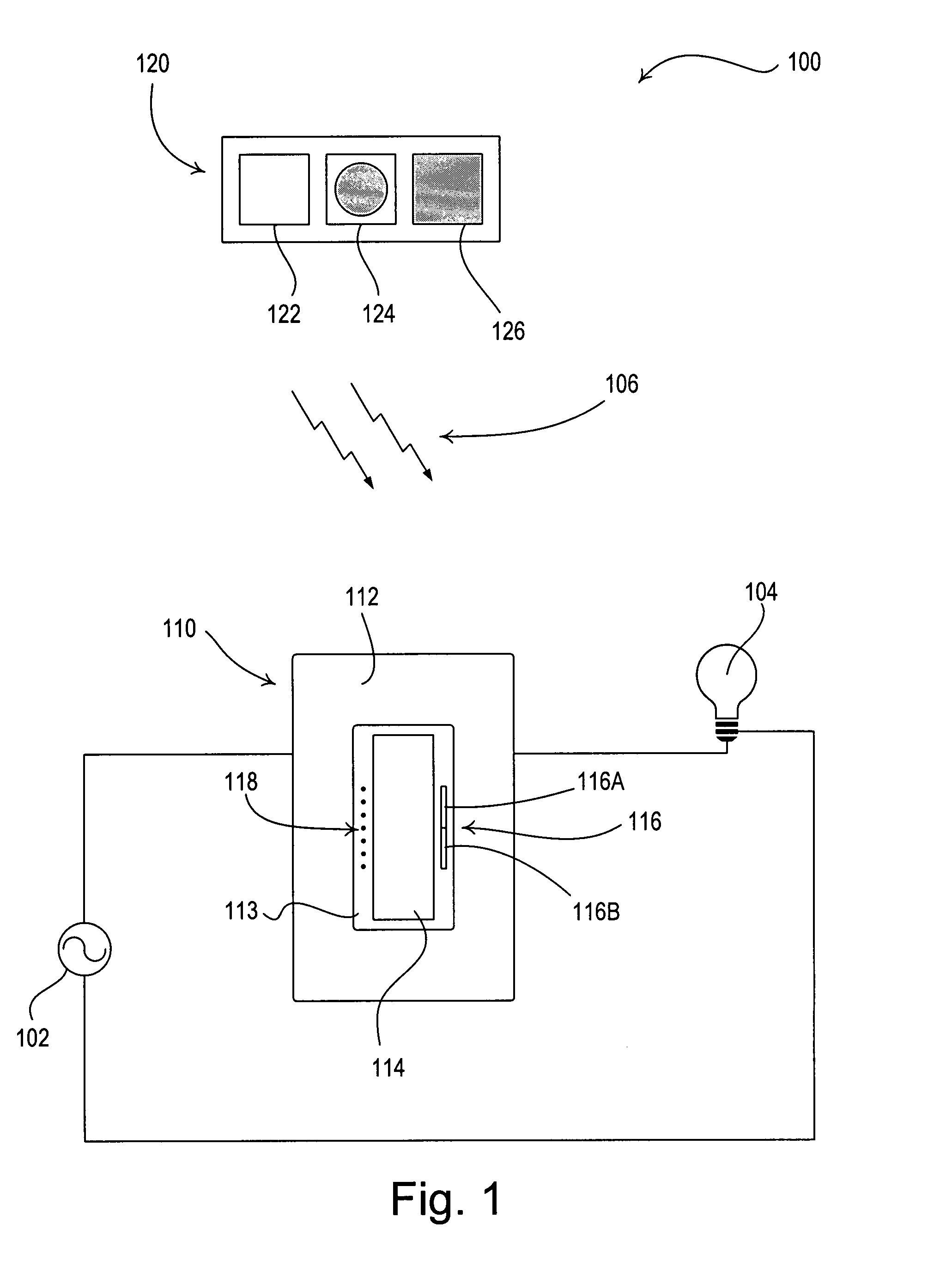
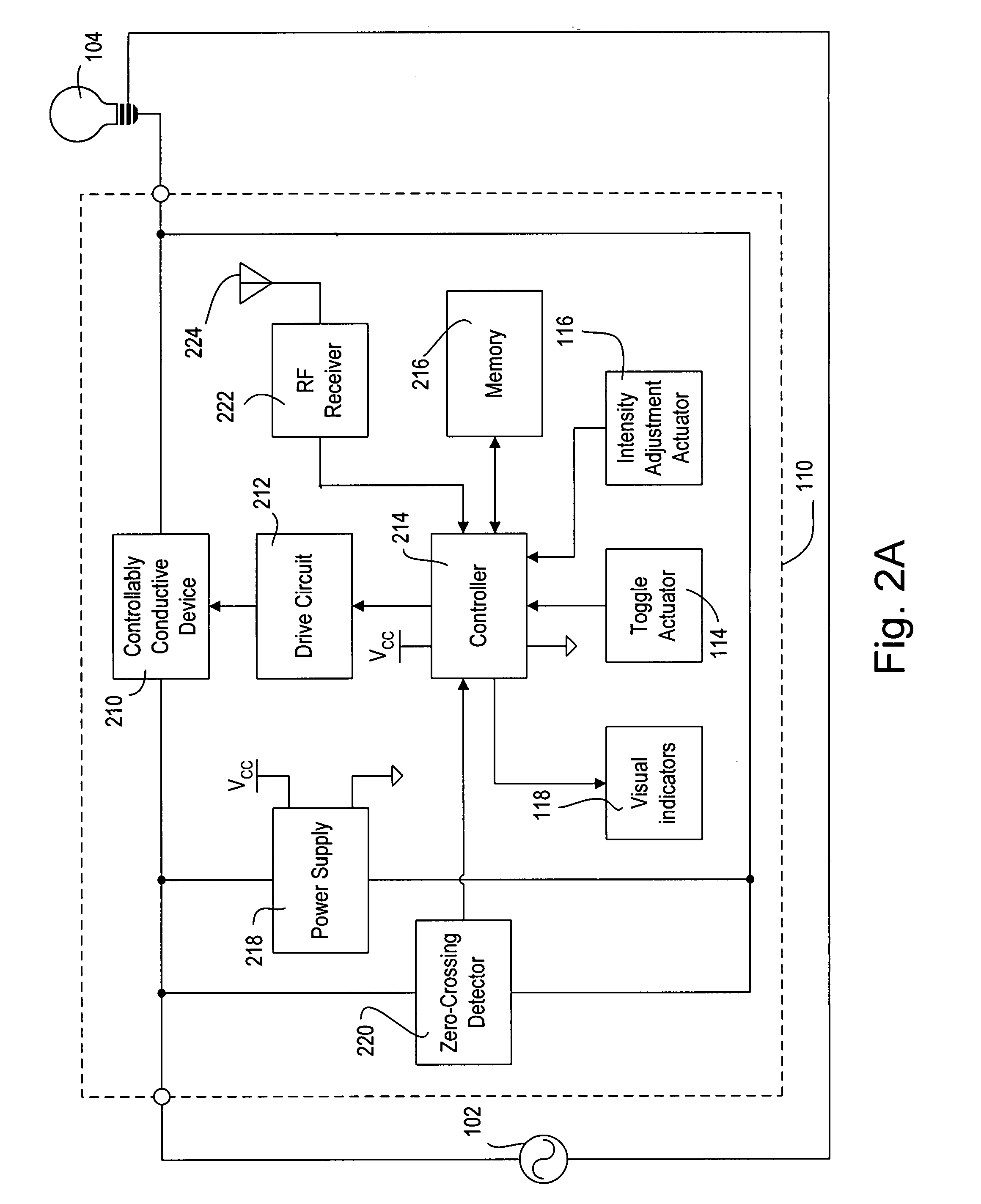
[0024]FIG. 1 is a simple diagram of an RF lighting control system 100 according to the present invention. The lighting control system 100 comprises a remotely-controllable load control device, i.e., a dimmer switch 110, and a remote control 120. Preferably, the dimmer switch 110 is adapted to be wall-mounted in a standard electrical wallbox. The dimmer switch 110 is operable to be coupled in series electrical connection between an AC power source 102 and an electrical lighting l...


PUM


Abstract

The present invention provides a method of programming a preset intensity of a dimmer switch from a radio-frequency (RF) remote control. A user is able to adjust the intensity of the lighting load to a new intensity and subsequently press and hold a preset button on the remote control to program the new intensity as the preset intensity. The remote control transmits a wireless transmission to the dimmer switch, which immediately responds to the actuation of the preset button by controlling the intensity of the lighting load to an old preset intensity. The dimmer switch then blinks a light-emitting diode representative of the new intensity to provide feedback that the dimmer switch is in the process of programming the preset intensity to the new intensity. Eventually, the dimmer switch stores the new intensity as the preset intensity and stops blinking the light-emitting diode.

Description

BACKGROUND OF THE INVENTION[0001]1. Field of the Invention[0002]The present invention relates to a wireless lighting control system for controlling the amount of power delivered to an electrical load from a source of alternating-current (AC) power, and more particularly, to a method of programming a lighting preset from a radio-frequency (RF) remote control.[0003]2. Description of the Related Art[0004]Control systems for controlling electrical loads, such as lights, motorized window treatments, and fans, are known. Such control systems often use radio-frequency (RF) transmission to provide wireless communication between the control devices of the system. One example of an RF lighting control system is disclosed in commonly-assigned U.S. Pat. No. 5,905,442, issued on May 18, 1999, entitled METHOD AND APPARATUS FOR CONTROLLING AND DETERMINING THE STATUS OF ELECTRICAL DEVICES FROM REMOTE LOCATIONS, the entire disclosure of which is hereby incorporated by reference.[0005]The RF lighting...

Claims


Application Information

Patent Timeline
Patent Type & Authority Patents(United States)
IPC IPC(8): H05B37/02
CPCH05B39/088H05B37/0272H05B47/19
Inventor NEWMAN, JR., ROBERT C.
Owner LUTRON TECH CO LLC
Learn More