
Method of fabricating a multilayer ceramic heating element

a ceramic heating element and multi-layer technology, applied in the direction of superimposed coating process, liquid/solution decomposition chemical coating, lighting and heating apparatus, etc., can solve the problems of large heat loss of combustion process to the cold combustion chamber walls, difficult production of exotic materials in high volume production settings, and completely compatible with other materials, so as to achieve small variations in thickness or composition

Inactive Publication Date: 2009-08-11
FEDERAL MOGUL WORLD WIDE
View PDF25 Cites 3 Cited by
  • Summary
  • Abstract
  • Description
  • Claims
  • Application Information

AI Technical Summary

Benefits of technology

[0012]The method provides the manufacture of multilayer ceramic heating elements such as those used for glow plugs to be automated and eliminates difficulties associated with plaster molds and the slurry injection equipment. Further, the sequential building up of thin layers produces a product that has smaller variations in thickness or composition than are possible with slip casting, injection molding or extrusion. The reduced stresses associated with thermal expansion differences between layers resists delamination of the layers during thermal cycling.

Problems solved by technology

With regard to the example of diesel engine applications, during starting and particularly in cold weather conditions, fuel droplets are not atomized as finely as they would be at normal running speeds, and much of the heat generated by the combustion process is lost to the cold combustion chamber walls.
While providing many benefits, these exotic materials can be difficult to manufacture in high volume production settings.
Sometimes, they are not entirely compatible with other materials, resulting in delamination and other problems.
Another common problem with specialty materials manifests as tolerance variations when formed in layers resulting from cumbersome and inefficient manufacturing techniques.
Conventional methods for manufacturing ceramic heating elements, such as glow plugs, involve complex manufacturing techniques.
The casting equipment used in this type of manufacturing process is complicated and requires a complex system of pumps and hoses to inject the slurry into the molds.
Moreover, the molds require careful preparation and have a very limited lifetime.
Other problems exist with this method, including changes in the mold that occur after each use and result in inconsistent layer thicknesses and inconsistent performance in the fired part.
Further, conventional methods are limited in their application and thickness of the layers.

Method used


Image

  • Method of fabricating a multilayer ceramic heating element
  • Method of fabricating a multilayer ceramic heating element
  • Method of fabricating a multilayer ceramic heating element

Examples


Embodiment Construction

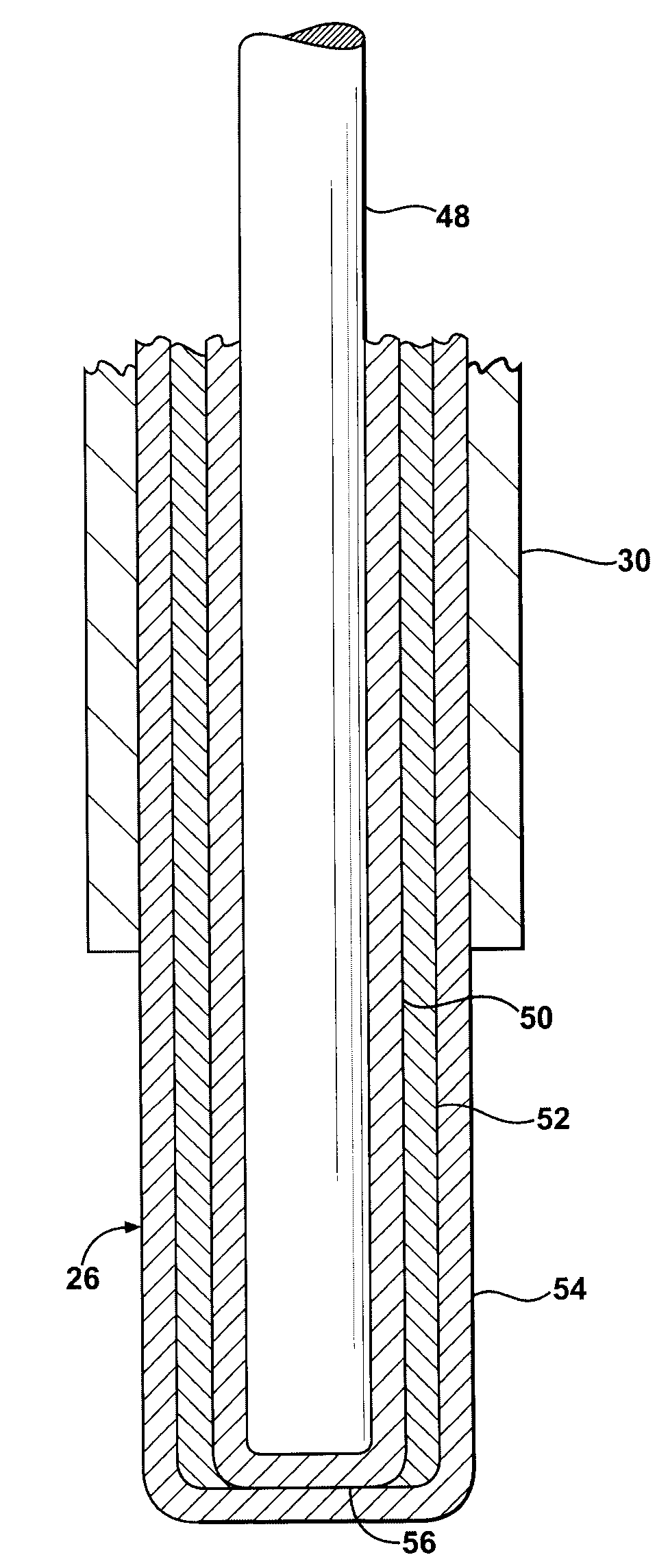
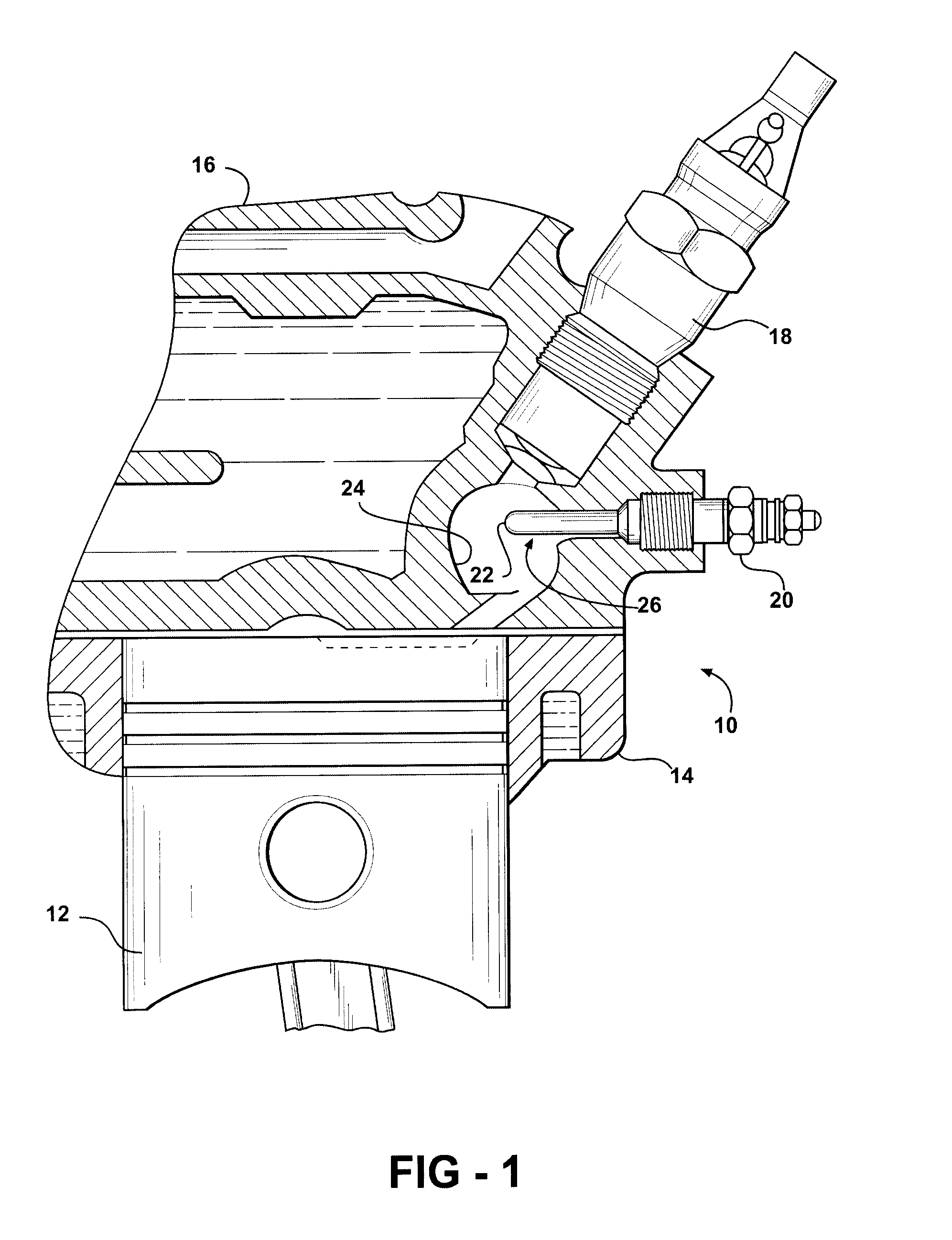
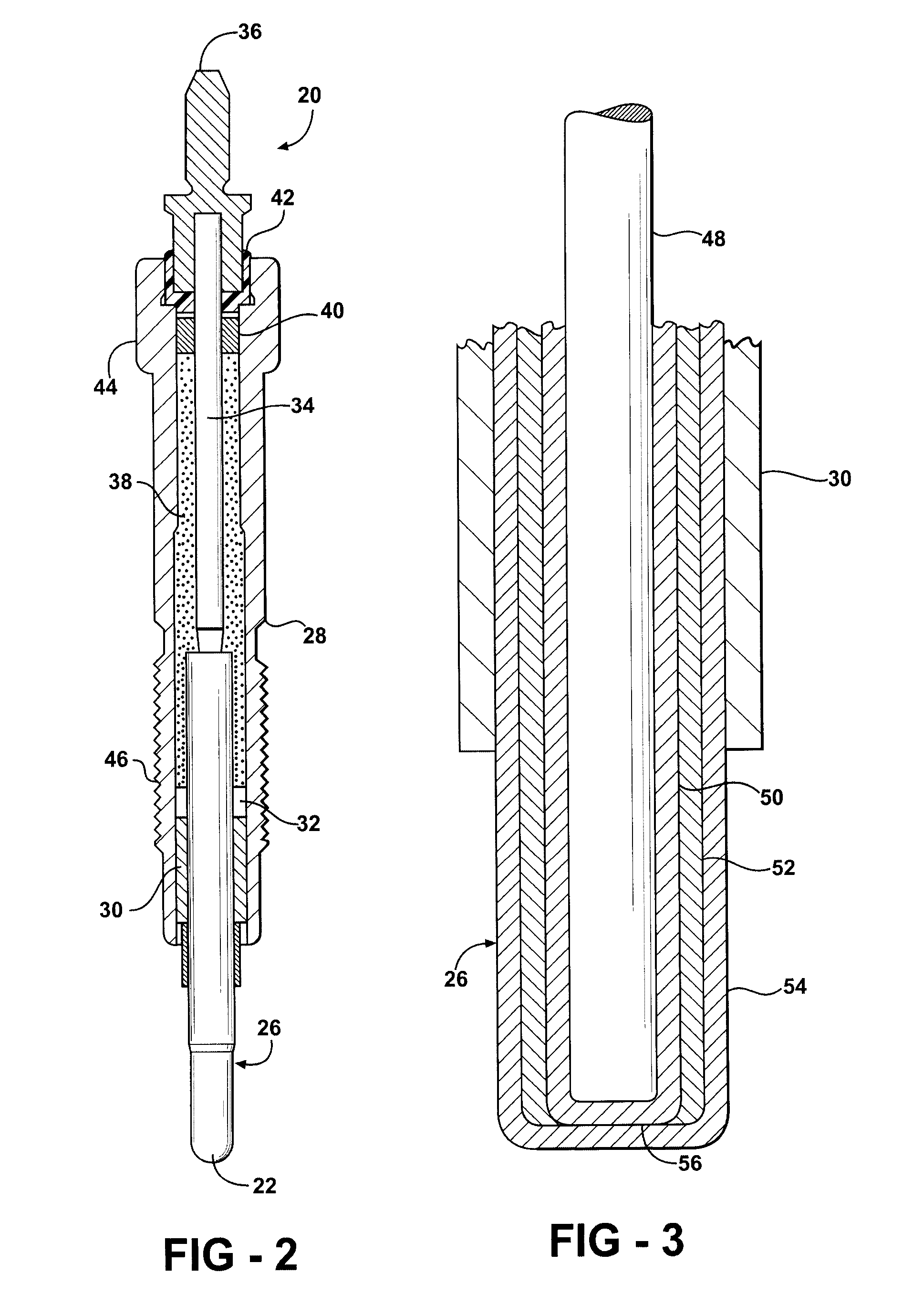
[0018]Referring to the Figures, wherein like numerals indicate like or corresponding parts throughout the several views, a diesel engine is generally shown at 10 in FIG. 1. The engine 10 includes a piston 12 reciprocating in a cylinder. The cylinder is formed in a block 14. A cylinder head 16 covers the block 14 to enclose a combustion chamber. An intake manifold routes through the cylinder head 16 and includes a fuel injector 18 which, at timed intervals, delivers a charge of atomized fuel into the combustion chamber. A glow plug, generally indicated at 20, includes a high temperature tip 22 positioned, in this example, within a pre-combustion chamber 24. The arrangement of components as illustrated in FIG. 1 is typical of one configuration style for a diesel engine. However, there are many other diesel engine types for which a glow plug 20 according to the invention is equally applicable. Furthermore, many other types of devices can utilize the subject glow plug 20, such as space ...


PUM

PropertyMeasurementUnit
thicknessesaaaaaaaaaa
thicknessaaaaaaaaaa

Abstract

A multilayer ceramic structure is formed by building up a plurality of layers by sequentially coating a substrate with a series of suspensions comprising particles in a fluid medium. A composition of the sequential layers are varied to produce a structure with the desired properties. The thickness of the layers can be controlled by rheological properties of the suspension and / or by the utilization of a gelling or coagulating agent. An advantage of this method is that complete drying between the subsequent coatings is not required.

Description

CROSS REFERENCE TO RELATED APPLICATIONS[0001]None.BACKGROUND OF THE INVENTION[0002]1. Field of the Invention[0003]The present invention relates to methods for manufacturing ceramic heating elements.[0004]2. Related Art[0005]Glow plugs can be utilized in any application where a source of intense heat is required for combustion. As such, glow plugs are used as direct combustion initiators in space heaters and industrial furnaces and also as an aid in the initiation of combustion when diesel engines must be started cold. Glow plugs are also used as heaters to initiate reactions in fuel cells and to remove combustible components from exhaust systems.[0006]With regard to the example of diesel engine applications, during starting and particularly in cold weather conditions, fuel droplets are not atomized as finely as they would be at normal running speeds, and much of the heat generated by the combustion process is lost to the cold combustion chamber walls. Consequently, some form of addi...

Claims


Application Information

Patent Timeline
Patent Type & Authority Patents(United States)
IPC IPC(8): B05D3/02
CPCF23Q7/001H05B3/141F23Q2007/004H05B2203/027H05B2203/01
Inventor MAY, JAMES L.HOFFMAN, JOHN W.WALKER, JR., WILLIAM J.
Owner FEDERAL MOGUL WORLD WIDE
Learn More