
Engine mode transition utilizing dynamic torque control

a technology of dynamic torque and engine mode, which is applied in the direction of electric control, speed sensing governors, instruments, etc., can solve the problems of increasing increasing the likelihood of mechanical malfunction, and increasing the longitudinal acceleration of the vehicle and/or excitation of the vehicle driveline. , to achieve the effect of improving engine efficiency, reducing the number of firing cylinders, and saving fuel

Inactive Publication Date: 2009-08-11
FORD GLOBAL TECH LLC
View PDF12 Cites 28 Cited by
  • Summary
  • Abstract
  • Description
  • Claims
  • Application Information

AI Technical Summary

Benefits of technology

This approach reduces torque transients and driveline excitation, thereby minimizing mechanical wear and the risk of malfunction, while maintaining efficient engine operation.

Problems solved by technology

However, the inventors herein have recognized some issues relating to the above approaches.
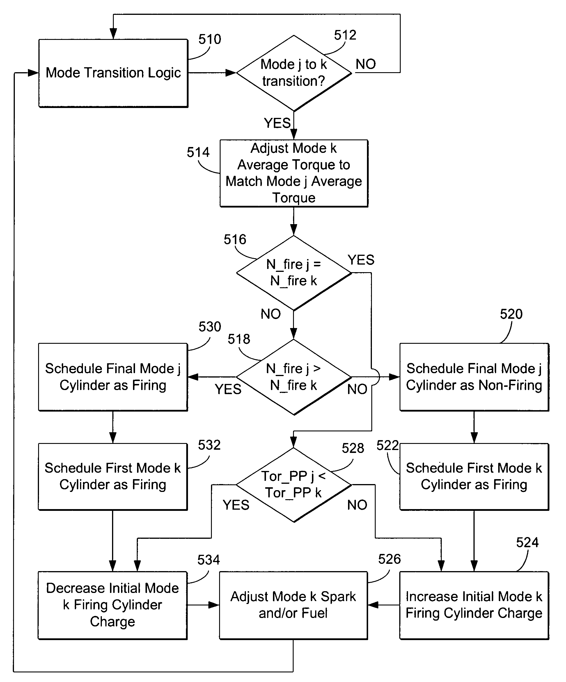
Specifically, in some conditions, engine transitions between different modes of operation may cause torque transients or discontinuities that can result in increased longitudinal acceleration of the vehicle and / or excitation of the vehicle driveline.
As such, the mode transitions may, in some cases, be perceived by the vehicle operator, may increase mechanical wear of vehicle components, or may increase the likelihood of mechanical malfunction, due to the torque transients occurring during the transition.

Method used


Image

  • Engine mode transition utilizing dynamic torque control
  • Engine mode transition utilizing dynamic torque control
  • Engine mode transition utilizing dynamic torque control

Examples


Embodiment Construction

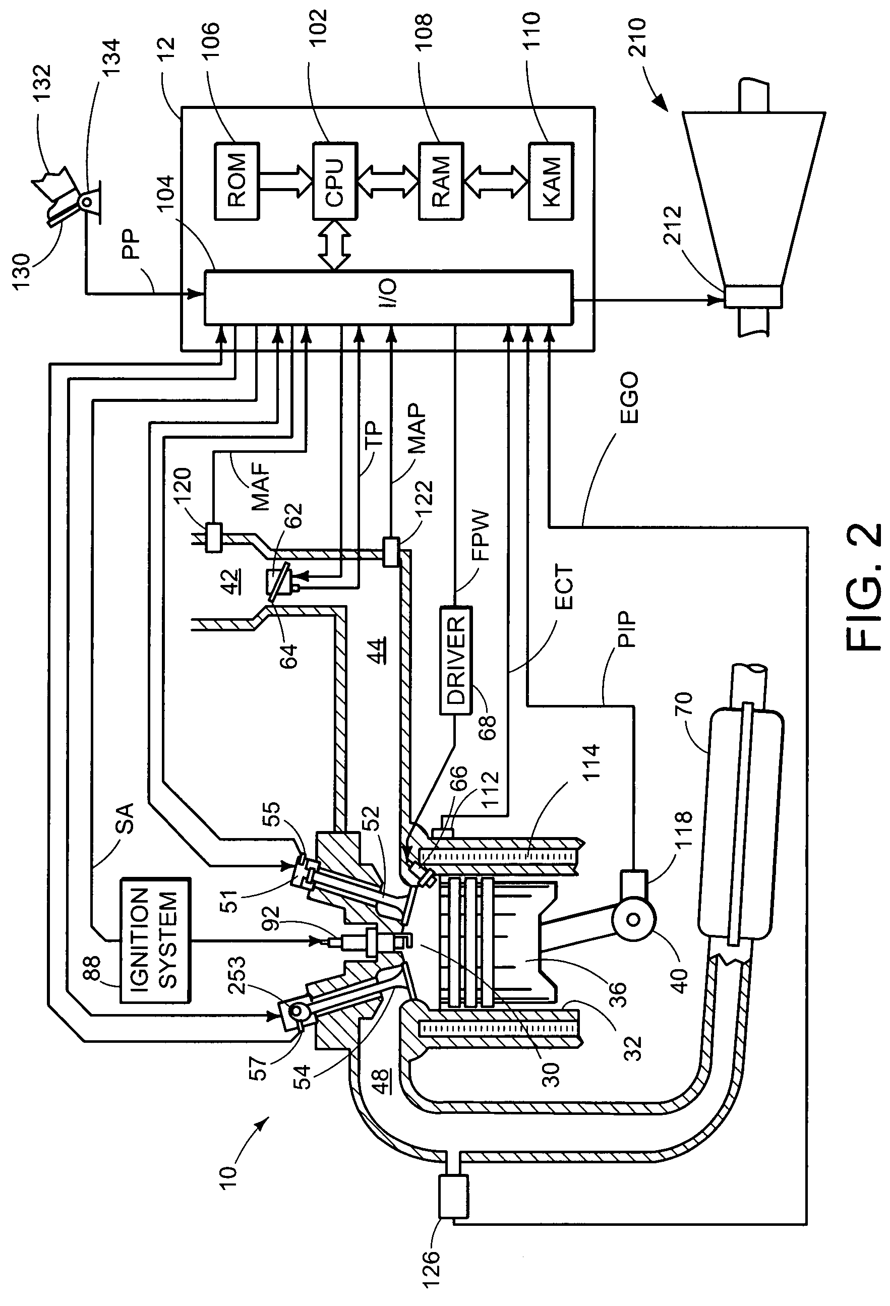
[0014]Referring to FIGS. 1 and 2, an example cylinder of multi-cylinder engine 10 is schematically shown. Engine 10 may be included, for example, with a vehicle propulsion system. Engine 10 may be controlled by a control system including controller 12 and by input from a vehicle operator 132 via an input device 130. In this example, input device 130 includes an accelerator pedal and a pedal position sensor 134 for generating a proportional pedal position signal PP. Combustion chamber (i.e. cylinder) 30 of engine 10 may include combustion chamber walls 32 with piston 36 positioned therein. Piston 36 may be coupled to crankshaft 40 so that reciprocating motion of the piston is translated into rotational motion of the crankshaft. Crankshaft 40 may be coupled to at least one drive wheel of the passenger vehicle via a transmission system 210. Further, a starter motor may be coupled to crankshaft 40 via a flywheel to enable a starting operation of engine 10.

[0015]Combustion chamber 30 may...


PUM


Abstract

A method of operating an engine having a plurality of cylinders, the method comprising of transitioning the engine from a first mode to a second mode, and temporarily adjusting an amount of torque produced by a cylinder of the engine for at least one cycle responsive to a difference in an amount of torque produced by a previous firing cylinder and a subsequent firing cylinder.

Description

BACKGROUND AND SUMMARY[0001]Some internal combustion engines can vary operation of one or more cylinders between different modes of operation depending on the operating conditions of the engine or other vehicle systems. As one example, at least a portion of the engine cylinders can be transitioned between a spark ignition (SI) mode and a homogeneous charge compression ignition (HCCI) mode in response to the level of torque requested by the vehicle operator. As another example, the number of firing cylinders may be reduced, under some conditions, by the use of cylinder deactivation, in order to conserve fuel and improve efficiency of the engine, while the number of firing cylinders may be increased where a greater amount of engine torque is requested. In this way, advantages associated with each mode of operation can be achieved while reducing or eliminating the disadvantages of each of the modes by selectively utilizing mode transitions.[0002]However, the inventors herein have recog...

Claims


Application Information

Patent Timeline
Patent Type & Authority Patents(United States)
IPC IPC(8): F02D13/06
CPCF02D41/307F02D41/0215F02D41/3058F02D41/3035
Inventor GIBSON, ALEX O'CONNORMICHELINI, JOHN OTTAVIO
Owner FORD GLOBAL TECH LLC
Learn More